Getting Started with LILYGO T-A7670G: ESP32 4G LTE & GPS Setup Guide
Learn how to connect the LILYGO T-A7670G development board to a cellular network. This step-by-step guide covers hardware features, board pinout, and the exact Arduino IDE code needed to get your ESP32 online via 4G LTE.
Welcome back to IoT Bhai!
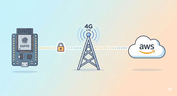
Are you looking for an all-in-one solution for your next cellular IoT project? Today, we are experimenting with a highly capable board: the LILYGO T-A7670G. This module integrates an ESP32, an A7670 4G LTE GSM module, and a dedicated Quectel GPS module onto a single PCB, making it a powerhouse for vehicle tracking and remote monitoring applications.
In this guide, we will walk through the hardware features and the initial setup to get your board connected to a 4G network.
Why Choose the LILYGO T-A7670G?
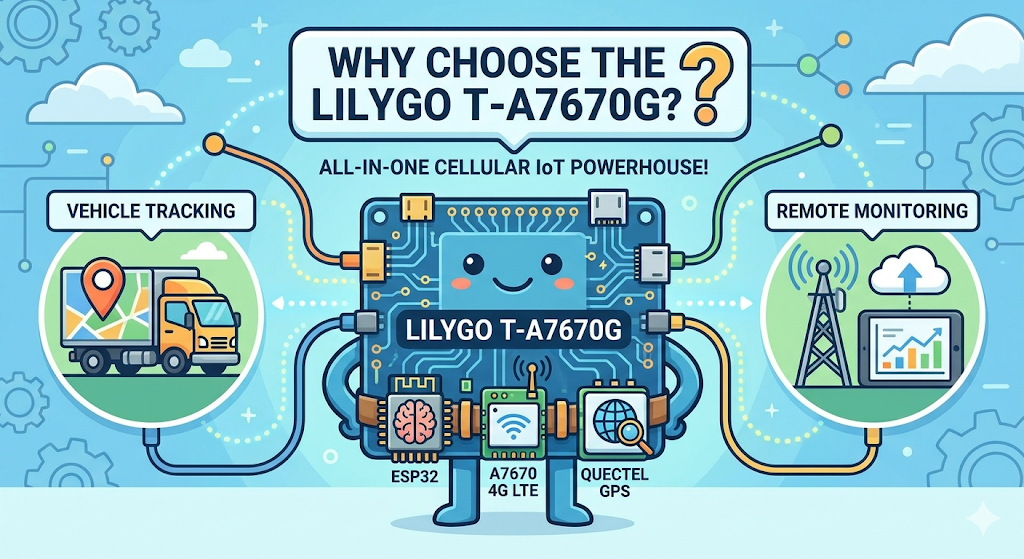
Before diving into the code, here is what makes this specific board stand out for local hardware experiments:
- Integrated Design: Combines the ESP32, 4G LTE connectivity, and a highly reliable Quectel GPS module, eliminating the need for messy jumper wires.
- Built-in Power Management: Features an integrated 18650 (3.7V) battery holder. The board automatically charges the battery when connected via USB.
- Solar Ready: Includes a dedicated 6V solar input port to power the board and charge the battery simultaneously.
- Easy Programming: Comes with a Type-C port for straightforward programming via the Arduino IDE.
Prerequisites: Hardware Checklist
To follow along with this setup, you will need:
- LILYGO T-A7670G Development Board
- Micro SIM Card (with an active data plan)
- USB Type-C Cable
Watch the Video Tutorial
If you prefer learning visually, I have put together a complete step-by-step video walkthrough of this project.
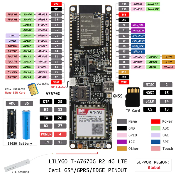
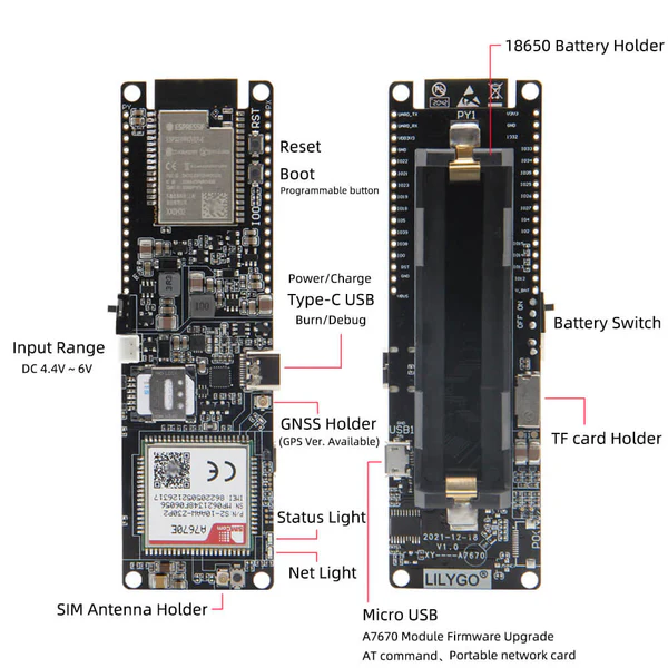
Pin Diagram of LILYGO T-A7670G
Since the LILYGO T-A7670G has the ESP32 and the modem integrated on the same PCB
Step 1: Hardware Assembly
- Insert the SIM Card: Carefully slide your Micro SIM card into the onboard slot on the back of the module.
- Attach Antennas: Connect the provided 4G LTE and GPS antennas to their respective U.FL ports on the board.
- Power Up: Connect the board to your computer using the USB Type-C cable.
Step 2: Software Setup
- Arduino IDE: Make sure you have the latest version installed.
- ESP32 Board Support: You must have the ESP32 board manager installed in your IDE. Need help? Check out my guide: How to Set Up ESP32 in Arduino IDE 2.0 (Windows/Ubuntu)
Step 3: Library Requirements (The TinyGSM Library)
To communicate with the modem using AT commands without writing complex parsing code, we rely on the TinyGSM library.
⚠️ Crucial Library Warning
The standard version of TinyGSM found in the Arduino Library Manager may not fully support the A7670G's specific AT command set yet.
For this tutorial to work, you must use the specific fork linked below:
- Download Library: https://github.com/lewisxhe/TinyGSM-fork
Installation Instructions:
- Download the repository as a
.zipfile from GitHub. - Open Arduino IDE.
- Go to Sketch -> Include Library -> Add .ZIP Library...
- Select the downloaded file.
Step 4: The Code
#define TINY_GSM_MODEM_A7670
#define SerialMon Serial
#define SerialAT Serial1
#define TINY_GSM_DEBUG SerialMon

#include <TinyGsmClient.h>

// ESP32 and A7670 pins
#define UART_BAUD 115200
#define MODEM_RESET_PIN 5
#define MODEM_PWKEY 4
#define MODEM_POWER_ON 12
#define MODEM_TX 26
#define MODEM_RX 27
#define MODEM_RESET_LEVEL HIGH
#define MODEM_GPS_ENABLE_GPIO -1

// GSM Internet Settings
#define GSM_PIN ""
const char apn[] = "internet";
const char gprsUser[] = "";
const char gprsPass[] = "";


#ifdef DUMP_AT_COMMANDS
#include <StreamDebugger.h>
StreamDebugger debugger(SerialAT, SerialMon);
TinyGsm modem(debugger);
#else
TinyGsm modem(SerialAT);
#endif


#include <Arduino.h>
#include <TinyGPS++.h>

TinyGPSPlus gps;


void setup() {
  SerialMon.begin(115200);
  delay(100);
  pinMode(MODEM_POWER_ON, OUTPUT);
  digitalWrite(MODEM_POWER_ON, HIGH);
  pinMode(MODEM_RESET_PIN, OUTPUT);
  digitalWrite(MODEM_RESET_PIN, !MODEM_RESET_LEVEL);
  delay(100);
  digitalWrite(MODEM_RESET_PIN, MODEM_RESET_LEVEL);
  delay(1000);
  digitalWrite(MODEM_RESET_PIN, !MODEM_RESET_LEVEL);
  pinMode(MODEM_PWKEY, OUTPUT);
  digitalWrite(MODEM_PWKEY, LOW);
  delay(100);
  digitalWrite(MODEM_PWKEY, HIGH);
  delay(1000);
  digitalWrite(MODEM_PWKEY, LOW);
  SerialMon.println("Wait ...");

  SerialAT.begin(115200, SERIAL_8N1, MODEM_RX, MODEM_TX);
  delay(3000);
  DBG("Initializing modem ...");

  String name = modem.getModemName();
  DBG("Modem Name:", name);
  delay(500);
  String modemInfo = modem.getModemInfo();
  SerialMon.print("Modem Info: ");
  SerialMon.println(modemInfo);

  if (GSM_PIN && modem.getSimStatus() != 3) {
    modem.simUnlock(GSM_PIN);
  }

  SerialMon.print("Waiting for network...");
  if (!modem.waitForNetwork()) {
    SerialMon.println(" fail");
    delay(10000);
    return;
  }
  SerialMon.println(" success");
  if (modem.isNetworkConnected()) {
    DBG("Network connected");
  }
  String ccid = modem.getSimCCID();
  DBG("CCID:", ccid);
  delay(500);
  String imei = modem.getIMEI();
  DBG("IMEI:", imei);
  delay(500);
  // Get operator name
  String operatorName = modem.getOperator();
  SerialMon.print("Operator: ");
  SerialMon.println(operatorName);
  delay(500);
  int csq = modem.getSignalQuality();
  DBG("Signal quality:", csq);
  delay(500);
  SerialMon.print("Connecting to APN: ");
  SerialMon.print(apn);
  if (!modem.gprsConnect(apn, gprsUser, gprsPass)) {
    SerialMon.println(" fail");
    ESP.restart();
  }
  SerialMon.println(" OK");
  delay(500);
  if (modem.isGprsConnected()) {
    SerialMon.println("GPRS connected");
  }
  IPAddress local = modem.localIP();
  DBG("Local IP:", local);
  delay(500);
  DBG("Asking modem to sync with NTP");
  modem.NTPServerSync("132.163.96.5", 20);
}

void loop() {
  static unsigned long lastPrint = 0;
  if (millis() - lastPrint > 5000) {  // every 5 seconds
    int signal = modem.getSignalQuality();
    SerialMon.print("Signal Quality (0–31): ");
    SerialMon.println(signal);

    // Optional: Check if still connected
    if (!modem.isNetworkConnected()) {
      SerialMon.println("⚠️ Network disconnected!");
    } else {
      SerialMon.println("✅ Network OK");
    }

    lastPrint = millis();
  }

  delay(100);
}
Step 5: Programming the Board
Once the library is securely installed, we can upload a simple test script to verify network connectivity.
- Open the Arduino IDE.
- Go to Tools -> Board and select ESP32 Dev Module.
- Select the correct COM port for your Type-C connection.
- Upload the test code
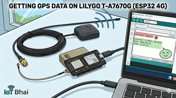
Step 6: Testing & Results
- Upload the Code: Connect your ESP32 to the PC and upload the sketch.
- Open Serial Monitor: Set baud rate to 115200.
- Observation:
- You will see the "Wait..." message while the code toggles the pins to boot the modem.
- Once initialized, it will print
Modem Info: SIMCOM_Ltd A7670G. - It will wait for the network (this can take 10-20 seconds).
- Upon success, you will see
GPRS connectedfollowed by a loop printing the Signal Quality (0-31) and Operator name.
Example Output:
Initializing modem...
Modem Info: A7670G
Waiting for network... success
Network connected
Signal Quality (0-31): 29
Connecting to APN: internet... OK
GPS connected
Local IP: 10.165.74.52
Syncing modem to sync with NTP...
Signal Quality (0-31): 29
Network OK
Signal Quality (0-31): 29
Network OK
Conclusion & What's Next
Congratulations! You have successfully powered up your LILYGO T-A7670G and established a stable 4G network connection. By using an integrated board, we've bypassed the common power and wiring headaches of older 2G modules, giving us a clean and reliable foundation for our projects.
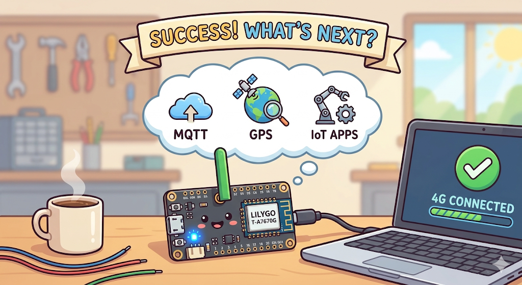
This initial setup is just the beginning. Now that your hardware is online, you are ready to dive into more advanced, local hardware experiments. In upcoming tutorials, we will explore:
- Sending and receiving MQTT payloads.
- Parsing real-time Quectel GPS data.
- Building practical IoT applications from scratch.
If you found this guide helpful, make sure to check out the full A7670G video tutorial on the IoT Bhai YouTube channel. Don't forget to subscribe for more hands-on IoT guides, and let me know in the comments what you plan to build with this powerful board!
Happy IoT coding!