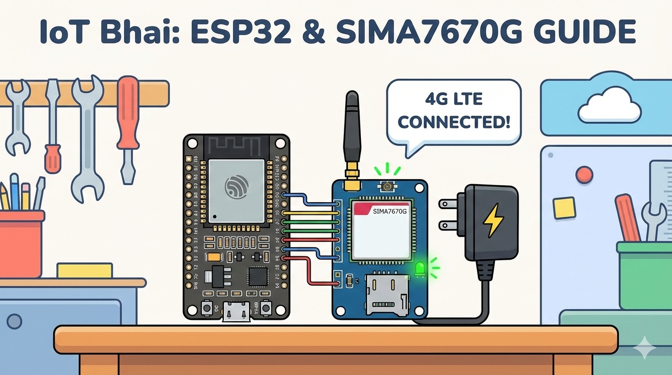
How to Connect SIM A7670G 4G Module with ESP32 | Complete Guide
Are you ready to upgrade your IoT projects from 2G to 4G? In this tutorial, we explain why the SIM A7670G is the best replacement for the SIM800L, how to wire it correctly to an ESP32, and providing the exact code to get you online.
Welcome back to IoT Bhai!
With 2G networks phasing out globally, it’s time to upgrade our IoT projects to broader, faster, and more reliable networks. If you’ve been using the classic SIM800 or SIM900 modules, the SIMCOM A7670G is the perfect upgrade path.
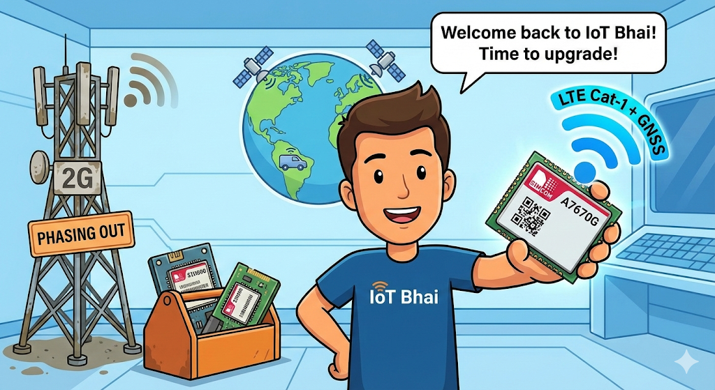
The A7670G is an LTE Cat-1 module with 2G fallback and—crucially—built-in GNSS (GPS/GLONASS/BeiDou) capabilities. This makes it an all-in-one powerhouse for vehicle tracking, remote monitoring, and high-speed data logging applications.
In this blog post, based on our latest YouTube video series, we are kicking things off with the fundamentals. We will cover:
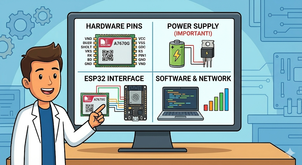
- Understanding the A7670G hardware pins.
- The critical importance of the power supply.
- Interfacing the module with an ESP32.
- Using the correct software libraries to check network connectivity and signal strength.
Let's dive into the world of 4G IoT.
Why Choose the SIMA7670G?
Before we start wiring, you might be wondering: Why should I switch to this specific module?
For years, the SIM800L was the king of hobbyist IoT. However, with the "2G Sunset" (telecom companies shutting down 2G towers), those older modules are becoming unreliable or completely obsolete. Here is why the SIMA7670G is the superior successor:
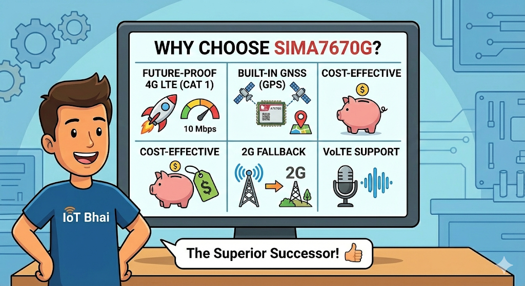
- Future-Proof 4G LTE (Cat 1): Unlike the high-speed Cat 4 modules used in smartphones (which are expensive and power-hungry), the A7670G uses LTE Cat 1. This is the "Sweet Spot" for IoT—it offers much faster speeds (up to 10 Mbps) and lower latency than 2G, but is still affordable and energy-efficient.
- Built-in GNSS (GPS): This is a game-changer. Usually, you would need a separate Neo-6M GPS module for tracking projects. The A7670G has integrated Multi-Constellation GNSS (GPS, GLONASS, BeiDou), allowing you to get precise location data and send it to the cloud using a single chip. [
Not all version have built-in GNSS] - Cost-Effective: It is one of the most affordable LTE modules on the market, making it accessible for hobbyists and scalable for commercial products.
- 2G Fallback: If you are in a remote area where 4G signal is weak, this module supports 2G fallback, ensuring your device stays connected even in poor coverage zones.
- VoLTE Support: It supports Voice over LTE, meaning you can still use it for projects that require making and receiving voice calls, just like the old GSM modules.
Watch the Video Tutorial
If you prefer learning visually, I have put together a complete step-by-step video walkthrough of this project.
Prerequisites: The Hardware Checklist
Before we begin, ensure you have the following components ready:
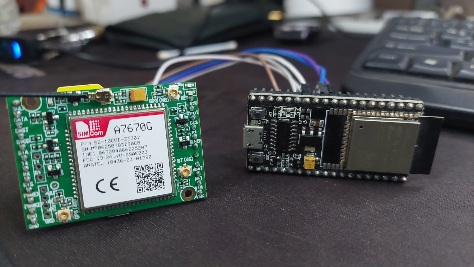
- ESP32 Development Board (e.g., DOIT DevKit V1 or similar).
- SIM A7670G Breakout Board (Ensure it comes with the LTE and GPS antennas).
- A Nano SIM Card with an active 4G data plan.
- Jumper Wires (Female-to-Male or Female-to-Female depending on your board headers).
- CRITICAL: A Stable External Power Supply (Rated 5V to 12V, capable of delivering at least 2.5A current).
Software:
- Arduino IDE: Make sure you have the latest version installed.
- ESP32 Board Support: You must have the ESP32 board manager installed in your IDE. Need help? Check out my guide: How to Set Up ESP32 in Arduino IDE 2.0 (Windows/Ubuntu)
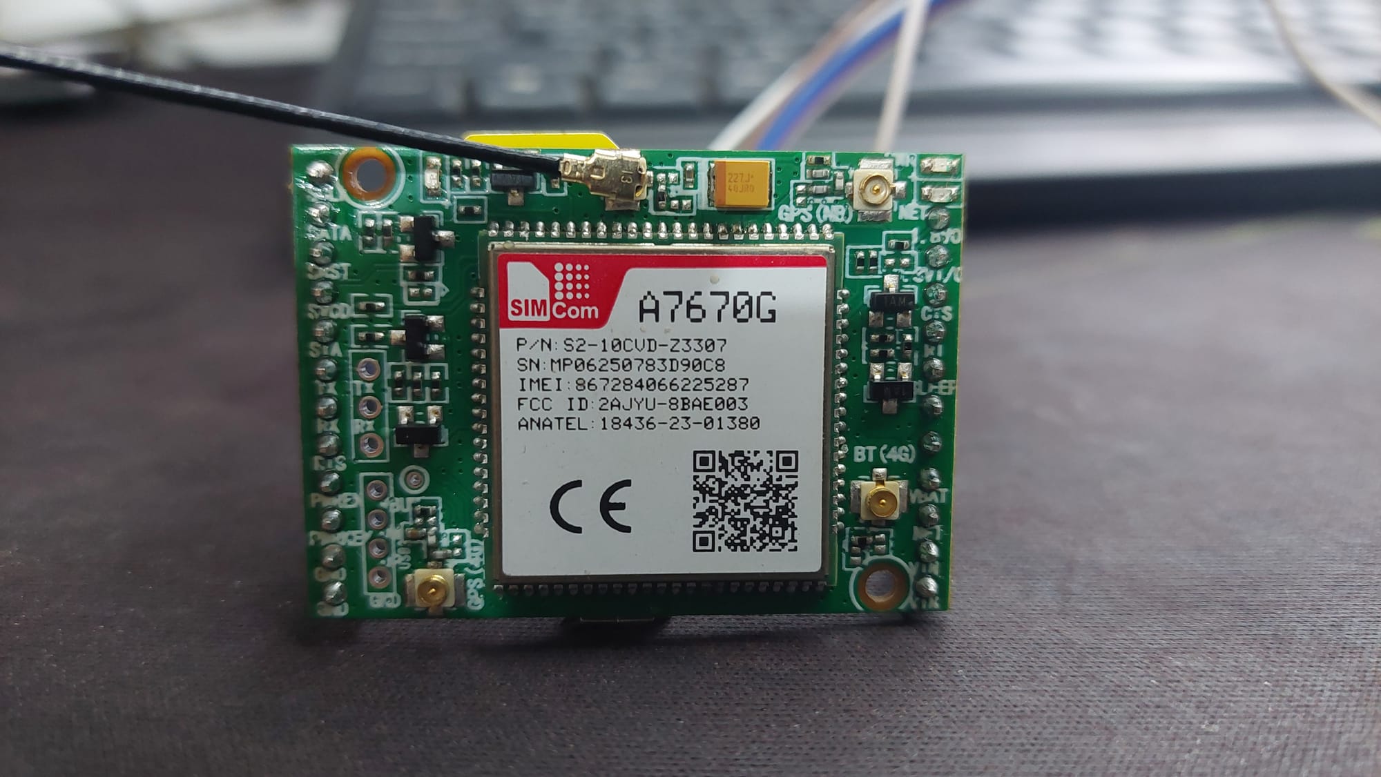
Step 1: Understanding the A7670G Module and Power Requirements
The A7670G breakout board has many pins, but for this specific configuration, we will use several GPIOs for control and communication, alongside critical power connections.
⚠️ The Golden Rule: Do Not Power from ESP32
As emphasized before, adequate power is crucial. The provided circuit diagram explicitly demonstrates using an external power source rather than relying on the ESP32.
- Need an External 5V/2A VCC source which will be connected directly to the VIN pin of the A7670G module.
- An External GND will be connected to the module's GND pin.
- Crucially, this external ground is shared with the ESP32 GND, creating a common ground connection required for data communication.
Also 5V Micro-USB Power is an option on the board so you can connect another micro-usb cable for powering the board
Step 2: Circuit Diagram and Wiring
We need to connect the A7670G module to the ESP32 following the specific pin configuration provided in the diagram. This setup utilizes UART pins for data, along with additional pins for hardware flow control (RTS) and power management (PWR EN, PWR KEY).
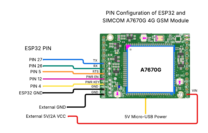
| ESP32 Pin | A7670G Pin Label | Description |
| PIN 27 | TX | ESP32 RX receives data from module TX |
| PIN 26 | RX | ESP32 TX sends data to module RX |
| PIN 5 | RTS | Request to Send (Flow Control) |
| PIN 12 | PWR EN | Power Enable control pin |
| PIN 4 | PWR KEY | Power Key (used for powering on/off the module) |
| ESP32 GND | GND | Common Ground with module and external power |
My Circuit
Step 3: Visual Status Check (No Code Required)
Before we upload any code or even connect the ESP32, you can verify if your SIM module is working and if your SIM card is active just by observing the onboard LEDs.
- Insert SIM & Antenna: Make sure your Nano SIM is inserted and the LTE antenna is connected.
- Power Up: Connect your external 5V power supply to the A7670G.
- Observe the LEDs:
- 🔵 Blue LED (Power):
- Solid Blue: The module is powered on and internal LDOs are working.
- If this is OFF: Check your power supply voltage and connections.
- 🟢 Green LED (Network):
- Blinking: The module has successfully found the network and registered.
- If this is NOT blinking (or solid ON): The module is either still searching, has no signal, or the SIM card is missing/inactive.
Success Condition: If you see the Blue LED solid and the Green LED blinking, your hardware is healthy, and the network is ready. You can now proceed to connect the ESP32!
Step 4: Software Setup (The TinyGSM Library)
To communicate with the modem using AT commands without writing complex parsing code, we rely on the TinyGSM library.
⚠️ Crucial Library Warning
The standard version of TinyGSM found in the Arduino Library Manager may not fully support the A7670G's specific AT command set yet.
For this tutorial to work, you must use the specific fork linked below:
- Download Library: https://github.com/lewisxhe/TinyGSM-fork
Installation Instructions:
- Download the repository as a
.zipfile from GitHub. - Open Arduino IDE.
- Go to Sketch -> Include Library -> Add .ZIP Library...
- Select the downloaded file.
Step 5: The Code
This specific code includes a "Modem Power-Up Sequence" in the setup() function. It manually toggles the Reset, Power Enable, and Power Key pins to ensure the modem wakes up correctly every time the ESP32 starts.
#define TINY_GSM_MODEM_A7670
#define SerialMon Serial
#define SerialAT Serial1
#define TINY_GSM_DEBUG SerialMon
#define GSM_PIN ""

#include <Arduino.h>
#include <TinyGsmClient.h>

// === SIM7600 Pin Definitions ===
#define MODEM_RESET_PIN 5
#define MODEM_PWKEY 4
#define MODEM_POWER_ON 12
#define MODEM_TX 26
#define MODEM_RX 27
#define MODEM_RESET_LEVEL HIGH

// === GPRS Config ===
const char apn[] = "internet";
const char gprsUser[] = "";
const char gprsPass[] = "";

// === Modem Object ===
TinyGsm modem(SerialAT);

void setup() {
  SerialMon.begin(115200);

  // Power ON the modem
  pinMode(MODEM_POWER_ON, OUTPUT);
  digitalWrite(MODEM_POWER_ON, HIGH);

  // Hardware reset
  pinMode(MODEM_RESET_PIN, OUTPUT);
  digitalWrite(MODEM_RESET_PIN, !MODEM_RESET_LEVEL);
  delay(100);
  digitalWrite(MODEM_RESET_PIN, MODEM_RESET_LEVEL);
  delay(2600);
  digitalWrite(MODEM_RESET_PIN, !MODEM_RESET_LEVEL);

  // Toggle PWRKEY to power up the modem
  pinMode(MODEM_PWKEY, OUTPUT);
  digitalWrite(MODEM_PWKEY, LOW);
  delay(100);
  digitalWrite(MODEM_PWKEY, HIGH);
  delay(1000);
  digitalWrite(MODEM_PWKEY, LOW);

  SerialMon.println("Wait ...");
  SerialAT.begin(115200, SERIAL_8N1, MODEM_RX, MODEM_TX);
  delay(3000);

  SerialMon.println("Initializing modem...");
  if (!modem.init()) {
    SerialMon.println("Failed to restart modem, delaying 10s and retrying");
    delay(10000);
    return;
  }

  String modemInfo = modem.getModemInfo();
  SerialMon.print("Modem Info: ");
  SerialMon.println(modemInfo);

  // Unlock SIM if needed
  if (GSM_PIN && modem.getSimStatus() != 3) {
    modem.simUnlock(GSM_PIN);
  }

  SerialMon.print("Waiting for network...");
  if (!modem.waitForNetwork()) {
    SerialMon.println(" fail");
    delay(10000);
    return;
  }
  SerialMon.println(" success");

  if (modem.isNetworkConnected()) {
    SerialMon.println("Network connected");
  }

  if (!modem.gprsConnect(apn, gprsUser, gprsPass)) {
    SerialMon.println("GPRS connect failed");
    return;
  }

  SerialMon.println("GPRS connected");
}

void loop() {
  // Do nothing
  int signal = modem.getSignalQuality();
  Serial.print("Signal quality (0–31): ");
  Serial.println(signal);

  bool registered = modem.isNetworkConnected();
  Serial.print("Network status: ");
  Serial.println(registered ? "Connected" : "Not connected");

  String op = modem.getOperator();
  Serial.print("Operator: ");
  Serial.println(op);
  delay(3000);
}
Step 6: Testing & Results
- Upload the Code: Connect your ESP32 to the PC and upload the sketch.
- Open Serial Monitor: Set baud rate to 115200.
- Observation:
- You will see the "Wait..." message while the code toggles the pins to boot the modem.
- Once initialized, it will print
Modem Info: SIMCOM_Ltd A7670G. - It will wait for the network (this can take 10-20 seconds).
- Upon success, you will see
GPRS connectedfollowed by a loop printing the Signal Quality (0-31) and Operator name.
Example Output:
Wait ...
Initializing modem...
Modem Info: SIMCOM_Ltd A7670G
Waiting for network... success
Network connected
GPRS connected
Signal quality (0–31): 28
Network status: Connected
Operator: Jio 4G
Conclusion & What's Next
Congratulations! You have successfully interfaced the A7670G 4G module with your ESP32. We have covered the critical power requirements, the correct wiring diagram, and the software logic needed to get your device online.
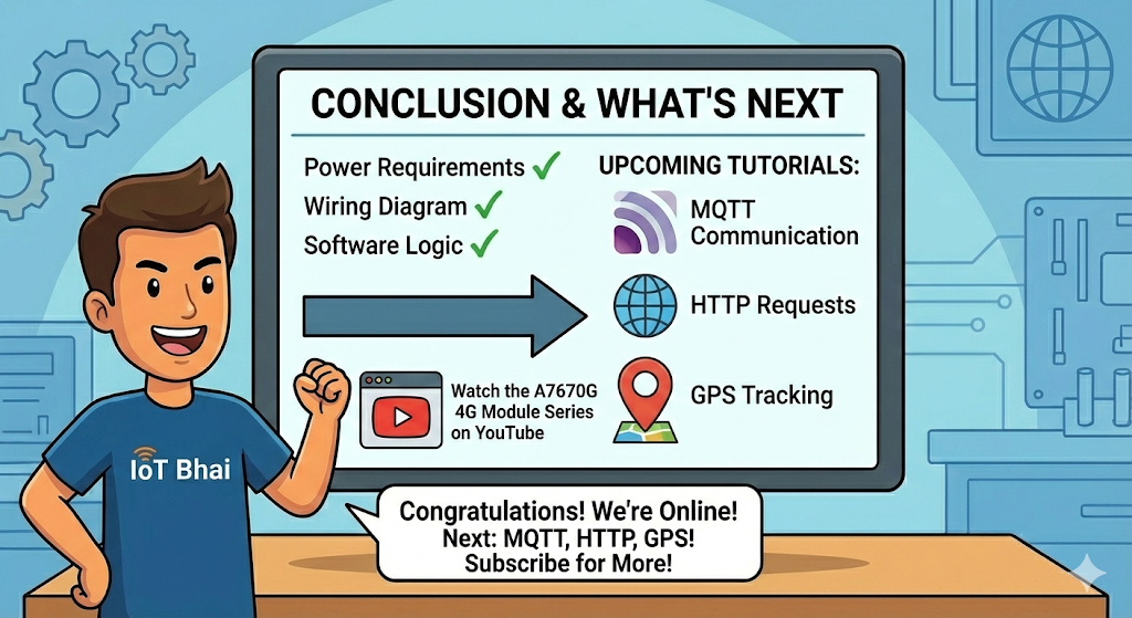
This is just the beginning of our journey with this powerful module. In upcoming tutorials, we will explore advanced features like Send & Receive SMS, MQTT communication, HTTP requests, and GPS tracking.
Watch the Full Series: To keep up with all the tutorials in this series and see the live demonstrations, make sure to save our dedicated playlist: 👉Watch the A7670G 4G Module Series on YouTube.
If you found this guide helpful, please share it with your fellow makers and subscribe to the IoT Bhai channel! Happy IoT coding!