How to Connect ESP32 to MQTT: ESP32 & MQTT Beginner’s Guide
Are you still using HTTP requests to control your IoT devices? If your ESP32 is constantly asking the server "Is there any data for me?" (polling), you might be draining your battery and wasting bandwidth.
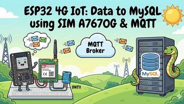
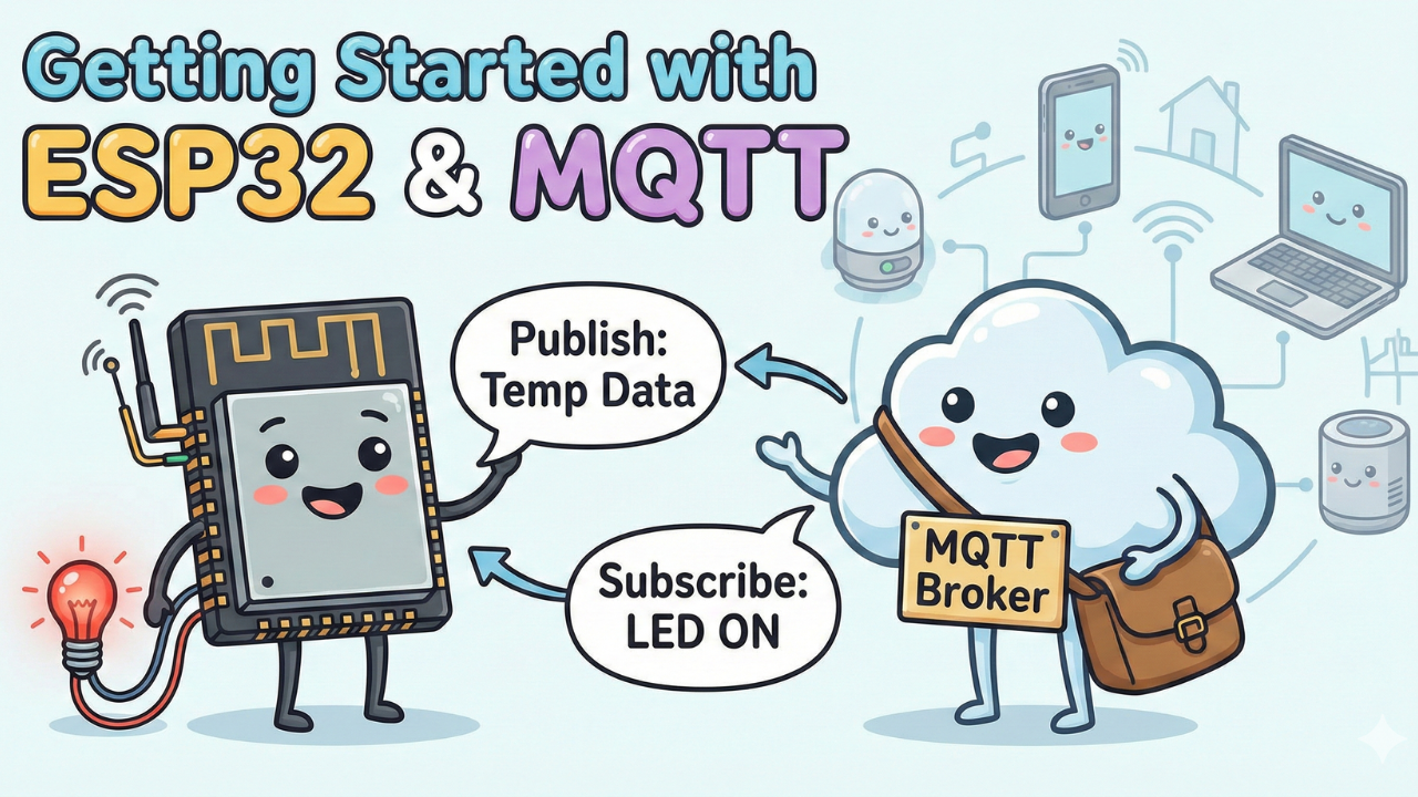
In this tutorial, we are going to upgrade your skills by switching to MQTT (Message Queuing Telemetry Transport). We will build a system where an ESP32 sends sensor data to a dashboard and listens for commands to control an LED instantly.
We will also implement a professional IoT feature called "Last Will and Testament" (LWT) to instantly detect if our device goes offline.
Why MQTT? (Vs. HTTP)
Before we wire anything up, it’s important to understand why we are using MQTT.
- HTTP (The Old Way): Think of this like checking your physical mailbox every 5 minutes to see if you have a letter. It’s inefficient and tiring.
- MQTT (The IoT Way): Think of this like a WhatsApp notification. You don't check for messages; the message arrives instantly when it's sent.
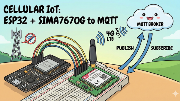
MQTT uses a Publisher/Subscriber model. The ESP32 doesn't need to know who is listening; it just "publishes" data to a specific topic, and anyone "subscribed" to that topic receives it.

What We Are Building
- Publisher: The ESP32 will send data (simulated temperature, WiFi signal strength, and uptime) to the broker every 5 seconds.
- Subscriber: The ESP32 will listen for "ON" or "OFF" commands to toggle an LED.
- Last Will: If the ESP32 is unplugged, the system will automatically alert us that the device is "Offline."
Watch the Video Tutorial
If you prefer learning visually, I have put together a complete step-by-step video walkthrough of this project. In the video, I demonstrate the hardware setup, explain the code logic in detail, and show the live bi-directional communication between the ESP32 and the MQTT broker.
Hardware Required
- ESP32 Development Board
- 1x LED (Any color)
- 1x 330Ω Resistor
- Breadboard and Jumper Wires
- Micro USB Cable
Software Tools
- Arduino IDE: Make sure you have the latest version installed.
- ESP32 Board Support: You must have the ESP32 board manager installed in your IDE. Need help? Check out my guide: How to Set Up ESP32 in Arduino IDE 2.0 (Windows/Ubuntu)
- MQTTX (A free desktop software to visualize data)
Step 1: The Circuit
The wiring is very straightforward. We are using the ESP32's GPIO capabilities.
- LED Anode (+): Connect to GPIO 27
- LED Cathode (-): Connect to GND via the 330Ω resistor.
Note: If you are using the external LED, ensure the resistor is in series to prevent burning out the LED.

Step 2: The Code Logic
We will be using the PubSubClient library for MQTT and ArduinoJson to format our data nicely.
Key Concepts in the Code:
- Topic Structure: We organize our data using a path format:
DeviceType/DeviceID/Function.- Data Topic:
ESP32/Unit1/data - Command Topic:
ESP32/Unit1/command - Status Topic:
ESP32/Unit1/status
- Data Topic:
- Non-Blocking Loop: Instead of
delay(5000), which pauses the brain of the ESP32, we use a timer check. This allows the ESP32 to receive LED commands while it waits to send the next temperature reading. - The "Last Will": During the connection setup, we tell the broker: "If I disconnect unexpectedly, please publish the message 'Offline' to my status topic."
Github
Github Link
/*
 * PROFESSIONAL MQTT EXPERIMENT - ESP32
 * * Features:
 * - Non-blocking Architecture (No delay())
 * - Automatic Reconnection (WiFi & MQTT)
 * - LWT (Last Will & Testament) for State Monitoring
 * - JSON Data Serialization
 * - Remote Command Handling
 */

#include <WiFi.h>
#include <PubSubClient.h>
#include <ArduinoJson.h>

// ==========================================
// 1. CONFIGURATION (Edit these)
// ==========================================
const char* ssid = "";
const char* password = "";

// MQTT Broker Settings (Using public HiveMQ for demo, change for production)
const char* mqtt_server = "broker.hivemq.com";
const int mqtt_port = 1883;
const char* mqtt_user = ""; // Leave blank for public brokers
const char* mqtt_pass = "";

// Unique Device ID (Must be unique on the broker)
const char* device_id = "ESP32_Pro_Unit_01";

// Topics (Structure: device_type/device_id/function)
const char* topic_telemetry = "esp32/unit01/data";   // Where we send sensor data
const char* topic_command   = "esp32/unit01/cmd";    // Where we listen for commands
const char* topic_status    = "esp32/unit01/status"; // LWT (Online/Offline)

// ==========================================
// 2. GLOBAL OBJECTS & VARIABLES
// ==========================================
WiFiClient espClient;
PubSubClient client(espClient);

// Timers for non-blocking delays
unsigned long lastMsgTime = 0;
const long interval = 5000; // Send data every 5 seconds

#define LED_PIN 2 // Onboard LED

// ==========================================
// 3. SETUP WIFI
// ==========================================
void setup_wifi() {
  delay(10);
  Serial.println();
  Serial.print("Connecting to WiFi: ");
  Serial.println(ssid);

  WiFi.mode(WIFI_STA);
  WiFi.begin(ssid, password);

  while (WiFi.status() != WL_CONNECTED) {
    delay(500);
    Serial.print(".");
  }

  Serial.println("");
  Serial.println("WiFi connected");
  Serial.print("IP address: ");
  Serial.println(WiFi.localIP());
}

// ==========================================
// 4. CALLBACK (Handle Incoming Messages)
// ==========================================
void callback(char* topic, byte* payload, unsigned int length) {
  Serial.print("Message arrived [");
  Serial.print(topic);
  Serial.print("] ");

  // Convert payload to string for easier handling
  String message;
  for (int i = 0; i < length; i++) {
    message += (char)payload[i];
  }
  Serial.println(message);

  // -- Command Logic --
  // Example: If we receive "ON", turn on LED
  if (String(topic) == topic_command) {
    if (message == "ON") {
      digitalWrite(LED_PIN, HIGH);
      // Feedback: Publish new state immediately
      client.publish(topic_telemetry, "{\"led\": \"ON\"}");
    } else if (message == "OFF") {
      digitalWrite(LED_PIN, LOW);
      client.publish(topic_telemetry, "{\"led\": \"OFF\"}");
    }
  }
}

// ==========================================
// 5. RECONNECT (The Engine Room)
// ==========================================
void reconnect() {
  // Loop until we're reconnected
  while (!client.connected()) {
    Serial.print("Attempting MQTT connection...");

    // --- LWT CONFIGURATION ---
    // define Last Will: Topic, QoS, Retain, Message
    // If this ESP32 dies, the Broker will post "offline" to the status topic automatically.

    if (client.connect(device_id, mqtt_user, mqtt_pass, topic_status, 1, true, "offline")) {
      Serial.println("connected");

      // Once connected, publish an announcement that we are alive (Retained = true)
      client.publish(topic_status, "online", true);

      // Resubscribe to command topics
      client.subscribe(topic_command);
    } else {
      Serial.print("failed, rc=");
      Serial.print(client.state());
      Serial.println(" try again in 5 seconds");
      delay(5000); // Blocking delay here is acceptable as we can't operate without connection
    }
  }
}

// ==========================================
// 6. MAIN SETUP
// ==========================================
void setup() {
  Serial.begin(115200);
  pinMode(LED_PIN, OUTPUT);

  setup_wifi();

  client.setServer(mqtt_server, mqtt_port);
  client.setCallback(callback);
}

// ==========================================
// 7. MAIN LOOP
// ==========================================
void loop() {
  // Ensure we stay connected
  if (!client.connected()) {
    reconnect();
  }
  client.loop(); // Keep MQTT alive

  // --- Non-Blocking Timer for Telemetry ---
  unsigned long now = millis();
  if (now - lastMsgTime > interval) {
    lastMsgTime = now;

    // Create a JSON Document
    JsonDocument doc; // ArduinoJson v7
    doc["device"] = device_id;
    doc["uptime"] = millis() / 1000;
    doc["wifi_rssi"] = WiFi.RSSI();

    // Add dynamic data (simulated sensor)
    doc["temp"] = random(20, 30);

    // Serialize JSON to String
    char buffer[256];
    serializeJson(doc, buffer);

    // Publish to MQTT
    Serial.print("Publishing data: ");
    Serial.println(buffer);
    client.publish(topic_telemetry, buffer);
  }
}
Code
Step 3: Visualization with MQTTX
Now that the code is running, we need a way to see the data and control the LED. We will use MQTTX.
- Connect: Open MQTTX and create a new connection using the same Broker URL (
broker.hivemq.com) and Port (1883).

- Subscribe: Click "New Subscription" and enter
ESP32/unit01/data. You should immediately see JSON data arriving every 5 seconds: - Control: In the text input area, change the topic to
ESP32/unit01/cmd. Typeonand hit send.

- Result: The LED on your ESP32 should light up instantly!

The "Killer Feature": Testing the Last Will
This is the coolest part of the experiment.
- Subscribe to the topic
ESP32/Unit01/statusin MQTTX. - You should see the message "Online".
- Now, physically unplug the USB cable from your ESP32.
- Watch MQTTX. Even though the device is dead, the Broker will automatically publish "Offline" to the status topic.

This is how professional IoT dashboards know when a sensor has run out of battery or lost connection.
Conclusion
You have successfully moved beyond simple HTTP requests and built a responsive, bi-directional IoT device using MQTT. In this tutorial I used a public free broker but you should try to build your own broker, here is step by step guide -
We covered:
- The efficiency of the Push vs. Pull model.
- Formatting data with JSON.
- Using "Last Will" for connection health checks.
Part 2
Make a web dashboard