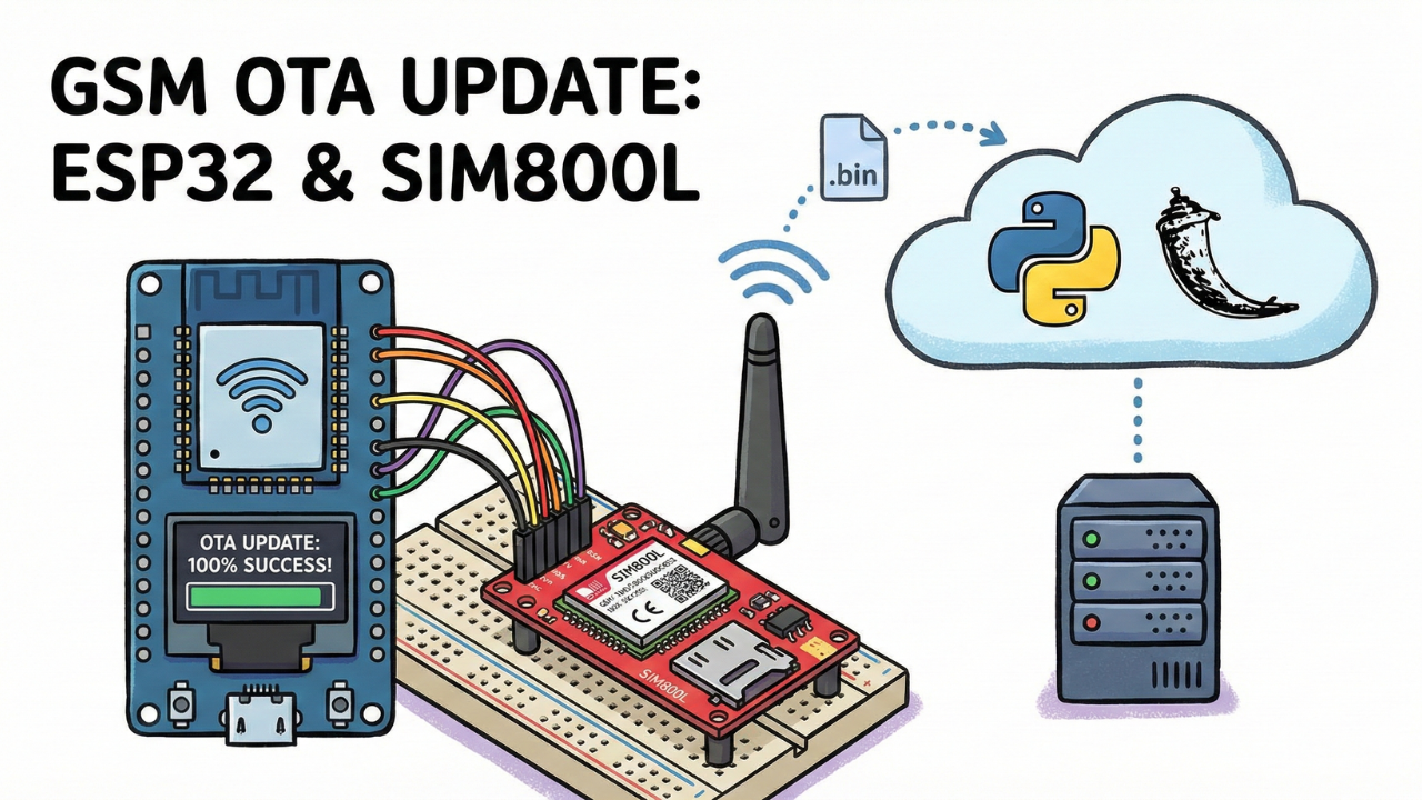
ESP32 OTA Firmware Update over GSM (SIM800L) with Python Flask Server(GSM IoT Series #6)
Learn how to perform remote OTA firmware updates on ESP32 using the SIM800L GSM module (2G). A complete guide to building a Python Flask update server for IoT devices without Wi-Fi coverage.
In the world of IoT, the ability to update your devices remotely is a superpower. We usually perform OTA (Over-The-Air) updates using Wi-Fi, which is fast and stable. But what if your device is deployed in a remote agricultural field or an industrial site where Wi-Fi isn't available?
In this post, I will show you how to perform OTA firmware updates using the SIM800L GSM module over a 2G network.
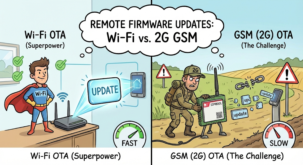
The Challenge: Wi-Fi vs. 2G GSM
Before we dive into the code, we need to understand why this is difficult.
- Wi-Fi OTA: Speed is ~150 KB/s, latency is low (20-50ms), and connection drops are rare.
- GSM (2G) OTA: Speed is only 3-5 KB/s, latency is high, and packet drops are common.
Because of these limitations, we cannot use standard OTA libraries. We need to write optimized code that downloads the firmware in small "chunks" and handles the unstable nature of 2G networks.
Comparison between WiFi vs GSM OTA
In the video, I showed a side-by-side comparison of how these two technologies behave. If you are coming from a Wi-Fi background, the limitations of 2G might shock you.
The Key Takeaway: Because 2G networks are slow and unstable, we cannot simply "download the file" like we do with Wi-Fi. If we try to download a large firmware file in one go, the connection will likely time out or break halfway through.
This is why our code uses a "Chunking Method":
- We don't try to swallow the whole file at once.
- We sip it in small 256-byte packets.
- We write each packet to flash memory immediately before asking for the next one.
This approach makes the update process slower (it takes a few minutes), but it makes it reliable enough to work on a 2G network.
Why Should You Care? (Real World Use-Cases)
You might be thinking, "2G is painfully slow... why not just use 4G or Wi-Fi?"
Here is why this experiment is actually a lifesaver:
- No More "Truck Rolls": Imagine you have 50 devices installed in different farms across the country. If you find a bug, do you really want to travel to every single location just to plug in a USB cable? OTA lets you fix bugs from your bedroom.
- Cost vs. Performance: 4G modules are awesome, but they are expensive (3x the price!). For simple sensor projects, the SIM800L is super cheap. This guide proves you can save money on hardware without sacrificing the ability to update it remotely.
- Network Coverage: Let's be real—Wi-Fi isn't everywhere. In many remote villages or agricultural fields, 4G signals can be weak, but 2G is almost always available. This method ensures your device stays connected even in the middle of nowhere.

📺 Watch the Video Tutorial
If you prefer learning visually, I have recorded a complete step-by-step walkthrough of this project. In the video, I demonstrate the hardware setup, explain the code logic in detail, and show the live bi-directional communication.
Required Component
Hardware
- SIM800L Module with the Header and Antenna soldered
- ESP32 Development Board
- Micro SIM Card (With Credit)
- Battery(Optional)
- DC-DC Booster Module (MT3608 or similar) if you use a Battery(Optional)
- 470 uF 25V Capacitor
- Breadboard
- Connecting wire
- MicroUSB Cable
Software Tools
- Arduino IDE: Make sure you have the latest version installed.
- ESP32 Board Support: You must have the ESP32 board manager installed in your IDE. Need help? Check out my guide: How to Set Up ESP32 in Arduino IDE 2.0 (Windows/Ubuntu)
- VPS (Linode/DigitalOcean) for the OTA Server (Localhost won't work for GSM).
- Python Flask (for the backend OTA Server).
About the Server: For this project, you cannot use "Localhost" or your home Wi-Fi IP address. You need a public cloud server (VPS). If you haven't set one up yet, check my guide on getting started with a Cloud VPS: 👉 Setting Up a Cloud VPS (Linode/DigitalOcean)
This is Part 6 of our GSM IoT Series. This is an advanced tutorial that requires a stable hardware setup.
If you are new here, or if this is your first time working with the SIM800L module, I strongly recommend you pause and complete the first two tutorials. They cover the essential wiring, power requirements, and network stability steps you need for today's project to work.
- Part 1: How to Connect SIM800L to ESP32 (Complete Wiring Guide)
- Part 2: SIM800L Network Troubleshooting Guide (Fixing Signal & Power Issues)
Why a Cloud VPS? (Why not my local PC?)
A common question I get is: "Can I just run the server on my laptop or a Raspberry Pi at home?"
The short answer is: No, not easily.
When your ESP32 + SIM800L is out in the "real world" using a cellular network, it is on the public internet. It cannot "see" your home computer or your local Wi-Fi network. Here is why you need a VPS:
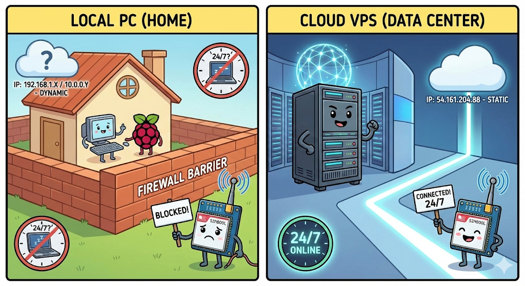
- The Firewall Barrier: Your home router (and your ISP) blocks incoming connections to protect you. A Cloud VPS is designed to be open and accessible from anywhere in the world.
- Static vs. Dynamic IP: Your home internet IP address likely changes every time you restart your router (Dynamic IP). A VPS provides a Static Public IP that never changes, ensuring your IoT devices always know exactly where to find the server.
- 24/7 Availability: Your laptop goes to sleep; a VPS stays online 24/7 in a secure data center, ensuring your IoT devices can check for updates at any time, day or night.
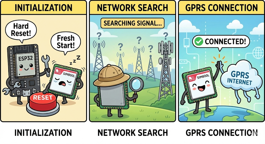
The OTA Process: How It Works Step-by-Step
In the video, I demonstrated the exact logic flow we use to ensure the update is safe and efficient. Here is the lifecycle of the operation:
1. System Initialization
- The ESP32 powers on and initializes the SIM800L module.
- It connects to the GPRS network using your SIM card's APN (getting a local IP address).
2. The Version Check
- Before downloading any heavy files, the ESP32 sends a small, lightweight HTTP GET request to our server's
/versionendpoint. - Comparison Logic:
- Server says:
1.0.1 - Device has:
1.0.0 - Result: The versions do not match. A New Firmware is Detected.
- Server says:
3. The Download (Streaming)
- The ESP32 requests the
firmware.binfile. - Because of the 2G speed limit, it does not download the whole file into RAM.
- Instead, it streams the file in 256-byte chunks. It writes one chunk to the ESP32's Flash memory, then requests the next chunk.
4. Verification & Reboot
- Once all bytes are downloaded and written, the standard
Updatelibrary verifies the integrity of the file. - If everything is correct, the ESP32 restarts itself.
- Upon reboot, it runs the new code (Version 1.0.1) and sends a final check to the server. This time, the versions match ("System Up to Date"), so it goes back to normal operation.
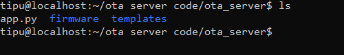
Project Structure
Resources & Downloads
You can find the complete source code for both the ESP32 Firmware and the Python Flask Server on my GitHub.
- 💾 GitHub Repository: Download Code Here
- 📂 Files Included:
Server_Code/: The Python Flask app (app.py,templates/,requirements.txt).ESP32_Code/: The C++ firmware (main.ino,config.h).
Setting Up the Python OTA Server
First, we need to get our server running on the VPS.
1. Download the Code Log in to your VPS using SSH and upload the files manually.
- Make sure you are in the project directly
- Install Dependencies We need to install Flask to run the web server. Run the following command:
pip install Flask(Note: If pip3 is missing, run sudo apt install python3-pip first)
- Allow Port 5000 By default, VPS firewalls block most ports. We need to open Port 5000 so the ESP32 can access it.
sudo ufw allow 5000
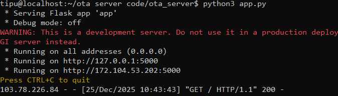
4. Run the Server Now, start the server application:
python3 app.py
If successful, you will see a message saying Running on http://0.0.0.0:5000.
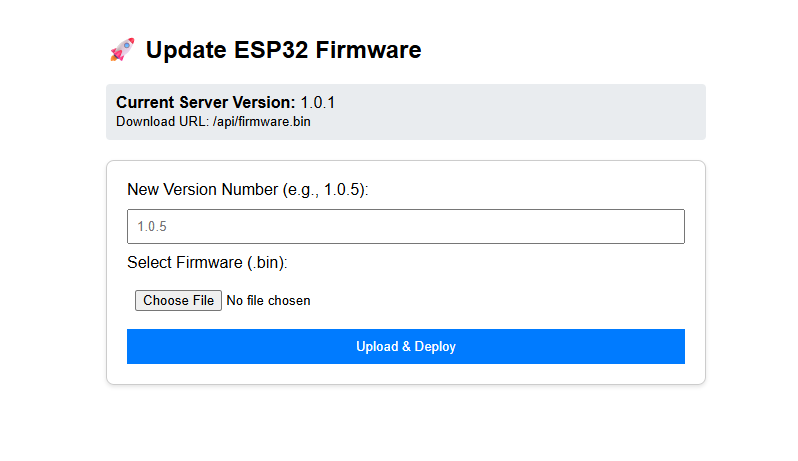
5. Verify via Browser Open your web browser and type: http://YOUR_VPS_IP:5000. You should see the OTA Dashboard.
Configure the ESP32 Firmware
Now, let's prepare the code that goes into the ESP32.
To keep our code clean and easy to edit, we will split it into two files:
config.h: Stores your settings (WiFi, APN, Pins) so you can change them easily.main.ino: Contains the actual logic and code.
Step 1: Install Library
We are using 1 main libraries for this project: TinyGSM (to handle AT commands)
Install these 3 library from arduino library manager
- TinyGSM by Volodymyr Shymanskyy (v0.12.0)
You can copy the code below directly into your Arduino IDE, or download the complete project files from my GitHub repository.
Step 2: Create the Config File
- Open Arduino IDE and create a new sketch.
- Click the small arrow icon (▼) near the top right of the editor tabs.
- Select "New Tab".
- Name the file
config.hand click OK.
Copy the code below and paste it into the config.h tab you just created.
Step 3: Paste the Configuration Code
Copy the code below and paste it into the config.h tab you just created.
// --- CONFIGURATION ---
const char currentVersion[] = "1.0.1";
const char apn[] = "internet"; // Change to your APN
const char gprsUser[] = "";
const char gprsPass[] = "";

// Server Details (HTTP Port 5000)
const char server[]   = "139.162.175.131"; // chnage with you server ip
const int  port       = 5000;
const char pathVersion[]  = "/api/version";
const char pathFirmware[] = "/api/firmware.bin";

// ESP32 and SIM800l pins
#define MODEM_TX 26
#define MODEM_RX 27
#define MODEM_RST 14
#define MODEM_DTR 25
#define MODEM_RING 34

#define BUILTIN_LED 2
Change the server IP with your vps ip and you can see current version is 1.0.1
So we will upload bin file of 1.0.1 to our ota server and then we downgread again from 1.0.1 to 1.0.0 and upload to device. So our device will get newer version from version url and start the ota update process.
Step 4: Paste the Main Code
Now, go back to the main tab (the one with the .ino extension) and paste the following logic code. Notice how it includes #include "config.h" at the top.
This is the main program file.
#define TINY_GSM_MODEM_SIM800
#define SerialMon Serial
#define SerialAT Serial1
#define TINY_GSM_DEBUG SerialMon
#define GSM_PIN ""

// Increase internal library buffer to prevent data loss
#define TINY_GSM_RX_BUFFER 1024

#include <TinyGsmClient.h>
#include <ArduinoHttpClient.h>
#include <Update.h>
#include "config.h"

TinyGsm modem(SerialAT);
TinyGsmClient client(modem);
HttpClient http(client, server, port);

void performOTA();
void checkAndPerformUpdate();

void setup() {
  SerialMon.begin(115200);
  delay(100);
  pinMode(BUILTIN_LED, OUTPUT);
  digitalWrite(BUILTIN_LED, LOW);

  pinMode(MODEM_RST, OUTPUT);
  digitalWrite(MODEM_RST, HIGH);
  delay(100);  // Keep low for 100ms
  digitalWrite(MODEM_RST, LOW);
  delay(100);
  digitalWrite(MODEM_RST, HIGH);
  delay(1000);

  SerialMon.println("Wait ...");
  // SIM800L standard baud is usually 9600 for stability on ESP32
  SerialAT.begin(9600, SERIAL_8N1, MODEM_TX, MODEM_RX);
  delay(3000);

  SerialMon.println("Initializing modem...");
  modem.restart();

  String modemInfo = modem.getModemInfo();
  SerialMon.print("Modem Info: ");
  SerialMon.println(modemInfo);

  SerialMon.print("Waiting for network...");
  if (!modem.waitForNetwork(60000L)) {
    SerialMon.println(" fail");
    delay(10000);
    return;
  }
  SerialMon.println(" success");

  SerialMon.print("Connecting to APN: ");
  SerialMon.print(apn);
  if (!modem.gprsConnect(apn, gprsUser, gprsPass)) {
    SerialMon.println(" fail");
    ESP.restart();
  }
  SerialMon.println(" OK");

  // Check for updates on boot
  checkAndPerformUpdate();
}

void loop() {
  delay(1800000);  // Check every 30 mins
  checkAndPerformUpdate();
}


void checkAndPerformUpdate() {
  if (!modem.isGprsConnected()) {
    SerialMon.println("GPRS disconnected, reconnecting...");
    modem.gprsConnect(apn, gprsUser, gprsPass);
  }

  SerialMon.println("Checking version...");

  // 1. Get Version Text
  http.stop();                         // Clean socket
  http.setHttpResponseTimeout(15000);  // 15s timeout

  int err = http.get(pathVersion);
  if (err != 0) {
    SerialMon.print("Connect failed: ");
    SerialMon.println(err);
    http.stop();
    return;
  }

  int statusCode = http.responseStatusCode();
  if (statusCode != 200) {
    SerialMon.print("Server error: ");
    SerialMon.println(statusCode);
    http.stop();
    return;
  }

  String serverVersion = http.responseBody();
  serverVersion.trim();
  http.stop();  // Close socket before next step

  SerialMon.printf("Server: %s | Device: %s\n", serverVersion.c_str(), currentVersion);

  if (serverVersion.equals(currentVersion)) {
    SerialMon.println("System up to date.");
  } else {
    SerialMon.println("New firmware detected. Starting SIM800L OTA...");
    delay(2000);  // Let modem settle
    performOTA();
  }
}

// ----------------------------------------------------------
// SIM800L OTA FUNCTION (Streaming Method)
// ----------------------------------------------------------
void performOTA() {
  SerialMon.println("Downloading Firmware...");

  // 1. Prepare HTTP Client
  http.stop();
  http.setHttpResponseTimeout(60000);  // 60s timeout for 2G

  // 2. Start Request
  int err = http.get(pathFirmware);
  if (err != 0) {
    SerialMon.print("Download start failed: ");
    SerialMon.println(err);
    http.stop();
    return;
  }

  int statusCode = http.responseStatusCode();
  long contentLength = http.contentLength();

  SerialMon.printf("Status: %d | Size: %ld bytes\n", statusCode, contentLength);

  if (statusCode != 200 || contentLength <= 0) {
    SerialMon.println("Invalid response.");
    http.stop();
    return;
  }

  // 3. Begin Update
  if (!Update.begin(contentLength)) {
    SerialMon.println("Not enough space for OTA");
    http.stop();
    return;
  }

  SerialMon.println("Writing to flash...");

  // 4. Stream Loop
  uint8_t buff[256];  // 256 bytes is safe for SIM800L
  size_t written = 0;
  size_t totalWritten = 0;
  size_t lastPrinted = 0;  // Track when we last printed to console
  unsigned long timeout = millis();

  while (http.connected() && (totalWritten < contentLength)) {
    if (http.available()) {
      // Read small chunk
      int len = http.read(buff, sizeof(buff));
      if (len > 0) {
        written = Update.write(buff, len);
        totalWritten += written;
        timeout = millis();  // Reset timeout on data arrival

        // --- NEW DISPLAY LOGIC ---
        // Print progress every 1024 bytes (1KB) or at the very end
        if ((totalWritten - lastPrinted >= 1024) || (totalWritten == contentLength)) {
          SerialMon.print(totalWritten);
          SerialMon.print(" | ");
          SerialMon.println(contentLength);
          lastPrinted = totalWritten;
        }
        // -------------------------
      }
    } else {
      delay(10);  // Wait for slow 2G data
    }

    // Watchdog: 60s timeout
    if (millis() - timeout > 60000) {
      SerialMon.println("\nTimeout: Data stopped flowing.");
      Update.abort();
      http.stop();
      return;
    }
  }

  // 5. Finalize
  if (totalWritten == contentLength && Update.end(true)) {
    SerialMon.println("\nOTA Success! Rebooting...");
    delay(1000);
    ESP.restart();
  } else {
    SerialMon.printf("\nError: Written %d / %d bytes\n", totalWritten, contentLength);
    Update.abort();
  }

  http.stop();
}
Generate the Binary File: We need the .bin file to upload to our server.
- In Arduino IDE, go to Sketch > Export Compiled Binary.
- This will create a
buildfolder inside your project directory containing the.binfile.
Step 3: Upload Firmware to Server
Let's pretend we have a new update.
- Go to your Web Dashboard (
http://YOUR_VPS_IP:5000). - Click Choose File and select the
.binfile you just generated. - Set the version number to 1.0.1 (or anything higher than what is currently on your ESP32).
- Click Upload.
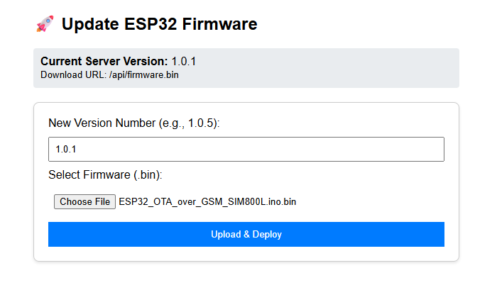
The server will save this file and update the version text.
Step 4: Testing the OTA Process
- Flash the ESP32: Upload the code to your ESP32 via USB cable. Make sure the code on the device has
currentVersion = "1.0.0". - Open Serial Monitor: Set baud rate to 115200.
- Watch the Magic:
- The ESP32 connects to GPRS.
- It checks the server: Server has
1.0.1, Device has1.0.0. - "New Firmware Detected"
- It begins downloading the update in chunks.
📸 Expected Serial Output
When your code uploads successfully, open your Serial Monitor (baud rate 115200).
⚠️ Important Note: The 2G Sunset
While the SIM800L is a fantastic, low-cost module for learning, please remember that it is a 2G-only device.
Many countries and cellular providers are shutting down their 2G towers to transition to 4G and 5G.
- For Learning: SIM800L is perfect.
- For Professional Products: I strongly recommend looking into 4G LTE modules like the SIM7600 or the A7670G. I have a separate playlist dedicated to the A7670 series on my channel if you want to future-proof your projects.
Conclusion
This experiment proves that while 2G GSM is slow, it is perfectly capable of handling OTA updates if we optimize our code. This is a game-changer for deploying low-cost IoT devices in remote areas of Bangladesh or anywhere with limited connectivity.