How to Connect SIMA7670G 4G LTE Module to MQTT with ESP32 | Complete IoT Guide
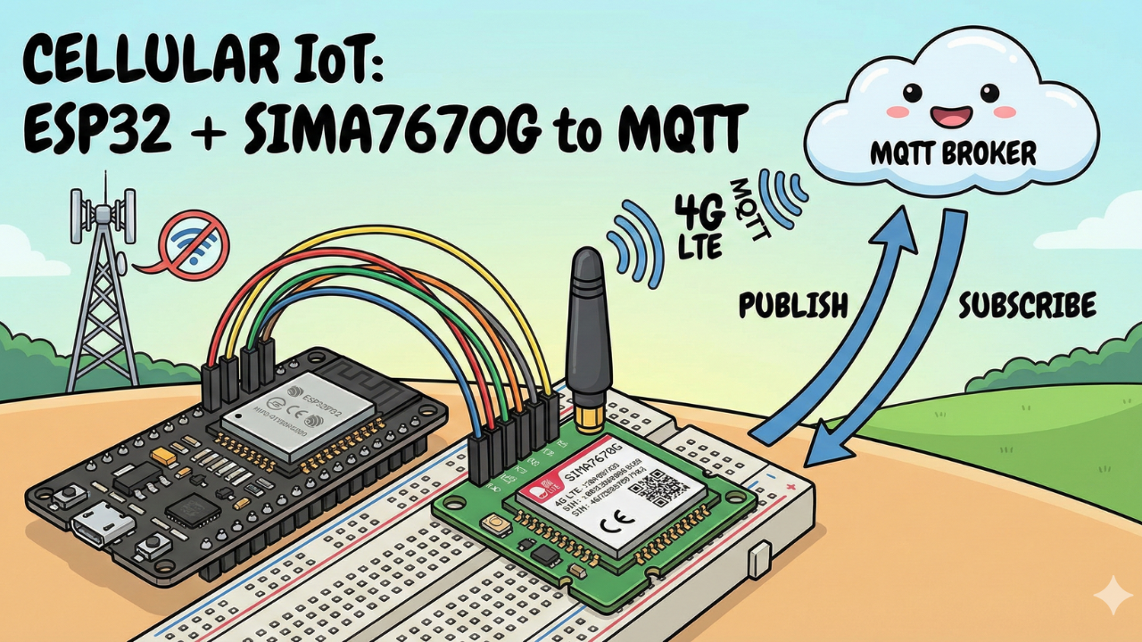
Take your IoT projects off the grid! This tutorial walks you through connecting the SIMA7670G 4G LTE module to an ESP32. We cover the critical power-up sequence, wiring diagrams, and provide full source code to Publish sensor data and Subscribe to remote commands via MQTT.
When building Internet of Things (IoT) projects, Wi-Fi is usually the go-to connectivity solution. It's cheap and easy. But what happens when your device needs to be deployed in a field, a moving vehicle, or anywhere far from a reliable router?

This is where cellular IoT comes in.
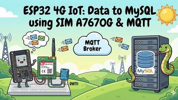
In this tutorial, we are taking a major step forward by moving away from standard Wi-Fi and using the SIMA7670G 4G LTE Module interfaced with an ESP32. We will connect this powerful combination to an MQTT Broker to enable two-way communication:
- Publishing Data: Sending status updates from the ESP32 up to the cloud.
- Subscribing to Data: Sending commands from the cloud down to the ESP32 to trigger actions.
MQTT (Message Queuing Telemetry Transport) is the standard, lightweight protocol for IoT, making it perfect for cellular data where bandwidth efficiency matters.
Let’s get started building truly remote IoT devices.
Video Tutorial
If you prefer to watch the step-by-step build, check out the full video tutorial on the IoTBhai YouTube channel here:
Video Tutorial
Prerequisites: The Hardware Checklist
Before we begin, ensure you have the following components ready:
- ESP32 Development Board (e.g., DOIT DevKit V1 or similar).
- SIM A7670G Breakout Board (Ensure it comes with the LTE and GPS antennas).
- A Nano SIM Card with an active 4G data plan.
- Jumper Wires (Female-to-Male or Female-to-Female depending on your board headers).
- CRITICAL: A Stable External Power Supply (Rated 5V, capable of delivering at least 2.5A current).
- Micro USB Cable (optional), if you want to power the sim module via usb port
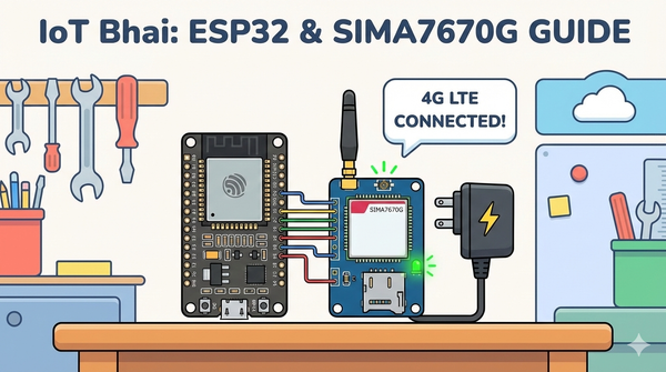
The Hardware Setup
The wiring remains the same as Part 1. If you have not wired your module yet, or if you are unsure about the power requirements, please refer to our detailed setup guide here:
👉Read Part 1: Connect SIM A7670G with ESP32 - Hardware & Wiring Guide
⚠️ Important: Ensure your SIM module is powered by an external 5V 2A power source, not the ESP32.
Software:
- Arduino IDE: Make sure you have the latest version installed.
- ESP32 Board Support: You must have the ESP32 board manager installed in your IDE. Need help? Check out my guide: How to Set Up ESP32 in Arduino IDE 2.0 (Windows/Ubuntu)
MQTT Broker
You need an MQTT broker to act as the "post office" for your messages.
- Testing: You can use the iotbhai free public broker
- broker: mqtt.iotbhai.io
- port: 1883
- Production (Recommended): For reliability and security, you should run your own broker on a VPS.
- Need help setting one up? Check out my previous guide on Setting up a VPS MQTT Broker.
Software Setup (The TinyGSM Library)
To communicate with the modem using AT commands without writing complex parsing code, we rely on the TinyGSM library.
⚠️ Crucial Library Warning
The standard version of TinyGSM found in the Arduino Library Manager may not fully support the A7670G's specific AT command set yet.
For this tutorial to work, you must use the specific fork linked below:
- Download Library: https://github.com/lewisxhe/TinyGSM-fork
Installation Instructions:
- Download the repository as a
.zipfile from GitHub. - Open Arduino IDE.
- Go to Sketch -> Include Library -> Add .ZIP Library...
- Select the downloaded file.
The Code
- Make sure you have installed the TinyGSM library (use the specific fork mentioned in the video description if the standard one fails).
- ⚠️ Note: Update the
apn,mqtt_broker, andcredentialsat the top before uploading.
#define TINY_GSM_MODEM_A7670
#define SerialMon Serial
#define SerialAT Serial1
#define TINY_GSM_DEBUG SerialMon
#define GSM_PIN ""

#include <PubSubClient.h>
#include <TinyGsmClient.h>

const char apn[] = "internet";
const char gprsUser[] = "";
const char gprsPass[] = "";

const char *mqtt_broker = "mqtt.iotbhai.io";
int port = 1883;
const char *mqtt_username = "user1";
const char *mqtt_password = "user1";
const char *publish_topic = "device/status";
const char *subs_topic = "device/command";

// === SIM7600 Pin Definitions ===
#define MODEM_RESET_PIN 5
#define MODEM_PWKEY 4
#define MODEM_POWER_ON 12
#define MODEM_TX 26
#define MODEM_RX 27
#define MODEM_RESET_LEVEL HIGH
#define BUILTIN_LED 2

#ifdef DUMP_AT_COMMANDS
#include <StreamDebugger.h>
StreamDebugger debugger(SerialAT, Serial);
TinyGsm modem(debugger);
#else
TinyGsm modem(SerialAT);
#endif


TinyGsmClient client(modem);
PubSubClient mqtt(client);
uint32_t lastReconnectAttempt = 0;
long lastMsg = 0;

void mqttCallback(char *topic, byte *message, unsigned int len) {
  Serial.print("Message arrived on topic: ");
  Serial.print(topic);
  Serial.print(". Message: ");
  String messageTemp;

  for (int i = 0; i < len; i++) {
    Serial.print((char)message[i]);
    messageTemp += (char)message[i];
  }
  Serial.println();
}

boolean mqttConnect() {
  SerialMon.print("Connecting to ");
  SerialMon.print(mqtt_broker);
  boolean status = mqtt.connect("GsmClientN", mqtt_username, mqtt_password);
  if (status == false) {
    SerialMon.println(" fail");
    ESP.restart();
    return false;
  }
  SerialMon.println(" success");
  mqtt.subscribe(subs_topic);
  return mqtt.connected();
}

void setup() {
  SerialMon.begin(115200);
  // Power ON the modem
  pinMode(MODEM_POWER_ON, OUTPUT);
  pinMode(BUILTIN_LED, OUTPUT);
  pinMode(BUILTIN_LED, LOW);

  digitalWrite(MODEM_POWER_ON, HIGH);

  // Hardware reset
  pinMode(MODEM_RESET_PIN, OUTPUT);
  digitalWrite(MODEM_RESET_PIN, !MODEM_RESET_LEVEL);
  delay(100);
  digitalWrite(MODEM_RESET_PIN, MODEM_RESET_LEVEL);
  delay(2600);
  digitalWrite(MODEM_RESET_PIN, !MODEM_RESET_LEVEL);

  // Toggle PWRKEY to power up the modem
  pinMode(MODEM_PWKEY, OUTPUT);
  digitalWrite(MODEM_PWKEY, LOW);
  delay(100);
  digitalWrite(MODEM_PWKEY, HIGH);
  delay(1000);
  digitalWrite(MODEM_PWKEY, LOW);

  SerialMon.println("Wait ...");
  SerialAT.begin(115200, SERIAL_8N1, MODEM_RX, MODEM_TX);
  delay(3000);

  SerialMon.println("Initializing modem...");
  if (!modem.init()) {
    SerialMon.println("Failed to restart modem, delaying 10s and retrying");
    delay(10000);
    return;
  }

  String modemInfo = modem.getModemInfo();
  SerialMon.print("Modem Info: ");
  SerialMon.println(modemInfo);
  // Unlock SIM if needed
  if (GSM_PIN && modem.getSimStatus() != 3) {
    modem.simUnlock(GSM_PIN);
  }
  String ccid = modem.getSimCCID();
  DBG("CCID:", ccid);
  String imei = modem.getIMEI();
  DBG("IMEI:", imei);
  String imsi = modem.getIMSI();
  DBG("IMSI:", imsi);
  String cop = modem.getOperator();
  DBG("Operator:", cop);

  int csq = modem.getSignalQuality();
  DBG("Signal quality:", csq);

  SerialMon.print("Waiting for network...");
  if (!modem.waitForNetwork()) {
    SerialMon.println(" fail");
    delay(10000);
    return;
  }
  SerialMon.println(" success");
  if (modem.isNetworkConnected()) {
    SerialMon.println("Network connected");
  }
  SerialMon.print("Connecting to APN: ");
  SerialMon.print(apn);
  if (!modem.gprsConnect(apn, gprsUser, gprsPass)) {
    SerialMon.println(" fail");
    ESP.restart();
  }
  SerialMon.println(" OK");
  if (modem.isGprsConnected()) {
    SerialMon.println("GPRS connected");
  }
  IPAddress local = modem.localIP();
  DBG("Local IP:", local);

  DBG("Asking modem to sync with NTP");
  modem.NTPServerSync("132.163.96.5", 20);
  // MQTT Broker setup
  mqtt.setServer(mqtt_broker, port);
  mqtt.setCallback(mqttCallback);
}

void loop() {
  if (!mqtt.connected()) {
    SerialMon.println("=== MQTT NOT CONNECTED ===");
    // Reconnect every 10 seconds
    uint32_t t = millis();
    if (t - lastReconnectAttempt > 10000L) {
      lastReconnectAttempt = t;
      if (mqttConnect()) {
        lastReconnectAttempt = 0;
      }
    }
    delay(100);
    return;
  }
  long now = millis();
  if (now - lastMsg > 10000) {
    lastMsg = now;
    send_data();
  }
  mqtt.loop();
}

void send_data() {
  mqtt.publish(publish_topic, "Hello From Device");
}
Source Code
How It Works
- Modem Initialization: Unlike standard serial modules, this setup toggles GPIO 4 and 5 to physically wake the modem from sleep mode. This is why you see the
digitalWritesequence at the start ofsetup(). - Network Registration: The
waitForNetwork()function ensures the SIM card has signal before attempting a GPRS data connection. - The Loop:
- The code checks connection status constantly.
mqtt.loop()handles incoming messages (Subscribing).send_data()triggers every 10 seconds to Publish "Hello From Device" to your broker.
Testing & Results
Once you have verified your wiring and updated the credentials in the code, it's time to test the cellular connection.
Live Test
1. Upload the Code: Connect your ESP32 to the PC and upload the sketch via Arduino IDE.
2. Open Serial Monitor: Set the baud rate to 115200.
3. Observation: You will first see the "Wait..." message while the ESP32 toggles the power pins to boot up the SIM module. This takes a few seconds.
If everything is wired correctly, your Serial Monitor output should look like this:
Wait ...
Initializing modem...
Modem Info: SIMCOM_Ltd A7670G
CCID: 8988...
IMEI: 8663...
Waiting for network... success
Network connected
Connecting to APN: internet... OK
GPRS connected
Asking modem to sync with NTP
Connecting to 172.236.236.214... success
4. Verification with MQTTX: Since the Serial Monitor only tells us the ESP32 is sending data, we need to verify it is actually arriving at the server.
- Open your MQTTX desktop client.
- Subscribe to the topic:
device/status - Result: Every 10 seconds, you should see a new message pop up:
"Hello From Device".
5. Testing Two-Way Communication:
- In MQTTX, publish a message to the topic:
device/command - Type any message (e.g., "Turn LED On") and click Send.
- Result: Check your Arduino Serial Monitor immediately. You should see:
Message arrived on topic: device/command. Message: Turn LED On
If you see these results, your cellular IoT device is fully operational!
Real-World Use Cases
- Vehicle Telematics & Asset Tracking: Perfect for tracking trucks, delivery vans, or shipping containers in real-time where Wi-Fi is unavailable.
- Smart Agriculture: Monitoring soil moisture, temperature, and automated irrigation systems in large fields far from the farmhouse.

- Remote Industrial Monitoring: Reading critical data (via Modbus) from remote generators, pumps, or solar grids and sending alerts to the cloud.
- Smart Vending Machines: Sending stock levels and sales data instantly to the central server for inventory management.
- Environmental Weather Stations: Solar-powered units deployed in forests or mountains to track rainfall, humidity, and air quality.
Conclusion: The World is Your Network
Congratulations! You have successfully built a cellular-connected IoT device. By combining the ESP32 with the SIMA7670G, you have broken free from the limitations of Wi-Fi range.
In this guide, we covered:
- Wiring the SIMA7670G module with the correct power sequence.
- Configuring the TinyGSM and PubSubClient libraries.
- Sending (Publishing) and Receiving (Subscribing) data over the 4G network using MQTT.

This project is the foundation for any professional IoT solution that requires remote monitoring. Whether you are building a vehicle tracker or a smart farm sensor, the communication logic remains exactly the same.
What's Next? Now that our data is reaching the MQTT broker, we need a way to visualize it. In the next tutorial, we will build a Real-Time Dashboard (using tools like Node-RED or a custom Web App) to turn these raw text messages into beautiful charts and gauges.
If you found this guide helpful, check out the video version on the IoTBhai YouTube Channel and subscribe for more industrial IoT tutorials!