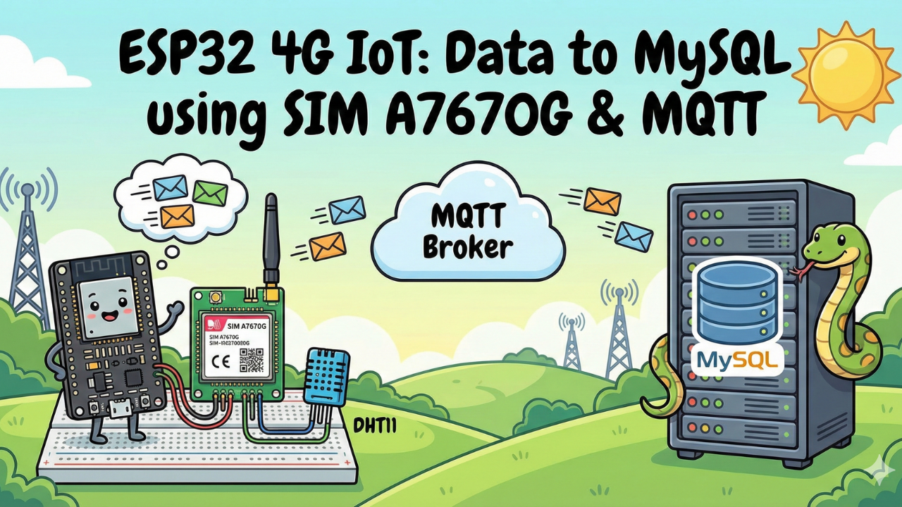
ESP32 4G IoT: Send Data to MySQL using SIM A7670G & MQTT
Take your IoT projects off the grid. Learn how to transmit real-time sensor data over 4G LTE using the ESP32 and SIM A7670G, and store it permanently in your own MySQL database using a secure MQTT pipeline. This guide covers everything from hardware wiring to the Python backend script.
In this guide, we are building the "Holy Grail" of IoT projects: a complete data pipeline that works anywhere in the world.
We will read Temperature & Humidity data from a DHT11 sensor, transmit it over the 4G LTE network using the SIM A7670G, and store it permanently in a MySQL Database via a custom Python script.
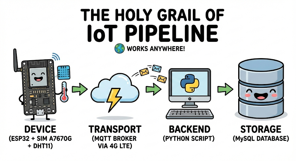
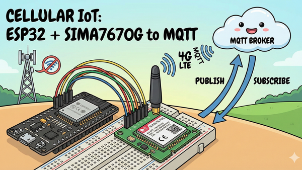
🚀 The Architecture
- Device: ESP32 + SIM A7670G reads sensor data.
- Transport: Sends JSON data to an MQTT Broker (4G LTE).
- Backend: A Python script listens to the MQTT topic.
- Storage: Python saves the decoded data into MySQL.
This is not just a toy example; this is the exact architecture used in professional vehicle tracking, industrial monitoring, and smart agriculture systems.
Video Tutorial
If you prefer to watch the step-by-step build, check out the full video tutorial on the IoTBhai YouTube channel here:
Prerequisites: The Hardware Checklist
Before we begin, ensure you have the following components ready:
- ESP32 Development Board (e.g., DOIT DevKit V1 or similar).
- SIM A7670G Breakout Board (Ensure it comes with the LTE and GPS antennas).
- A Nano SIM Card with an active 4G data plan.
- Jumper Wires (Female-to-Male or Female-to-Female depending on your board headers).
- CRITICAL: A Stable External Power Supply (Rated 5V, capable of delivering at least 2.5A current).
- Micro USB Cable (optional), if you want to power the sim module via usb port
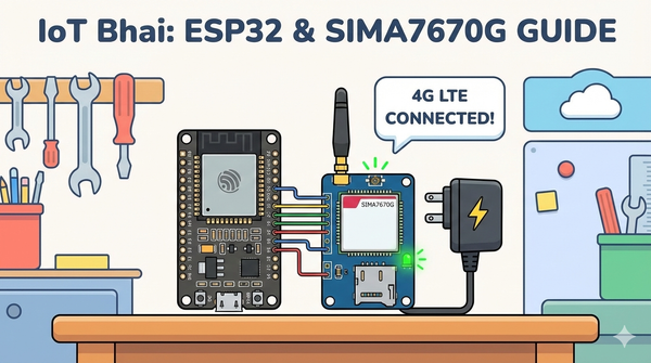
🛠️ Step 1: Hardware Setup
The wiring remains the same as Part 1. If you have not wired your module yet, or if you are unsure about the power requirements, please refer to our detailed setup guide here:
👉Read Part 1: Connect SIM A7670G with ESP32 - Hardware & Wiring Guide
⚠️ Important: Ensure your SIM module is powered by an external 5V 2A power source, not the ESP32.
🛠️ Step 2: Software Setup
- Arduino IDE: Make sure you have the latest version installed.
- ESP32 Board Support: You must have the ESP32 board manager installed in your IDE. Need help? Check out my guide: How to Set Up ESP32 in Arduino IDE 2.0 (Windows/Ubuntu)
- If you haven't set up your VPS, follow this guide: 👉Initial Server Setup For Your New VPS
- We need a Cloud MQTT Broker, and check out my previous guide on Setting up a VPS MQTT Broker
- Note: For testing, you can use the public broker
mqtt.iotbhai.io, but for production, we recommend your own VPS.
- Note: For testing, you can use the public broker
- We Need MySQL Database installed on VPS I have a step-by-step guide for that, too 👉Read Guide: How to Install MySQL on Linux VPS & Secure Remote Access.
❓ Why Do We Need a VPS?
You might wonder: "Can't I just run this on my laptop?"
Here is why a Cloud Server (VPS) is mandatory for 4G IoT:
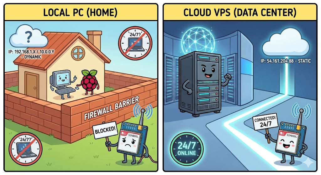
- The "No Public IP" Problem: Mobile networks use firewalls (CGNAT) that block incoming connections. You cannot "call" your ESP32 directly. A VPS provides a Static IP, acting as a permanent meeting point for your devices.
- 24/7 Reliability: Laptops sleep and lose Wi-Fi. A VPS runs 24/7/365 in a datacenter, ensuring you never miss a single data packet.
- Data Privacy: Public brokers (like HiveMQ) expose your data to everyone. A VPS allows you to run a private, password-protected broker that only you can access.
| Feature | Local PC / Public Broker | Your Own VPS |
| Connection | Blocked by Mobile Network | Always Accessible (Static IP) |
| Uptime | Low (Sleep/Reboots) | 99.9% Always On |
| Security | Zero (Public) | Encrypted & Private |
🗄️ Step 3: Database Setup
Now, we need a place to store our data. We will use MySQL, the world's most popular open-source database.
If you don't have MySQL installed on your Linux VPS yet, I have a step-by-step security guide for that too: 👉Read Guide: How to Install MySQL on Linux VPS & Secure Remote Access
Create the Table
Once your MySQL server is running, log in (via SSH or Workbench) and run these SQL commands to create the database and table for this project:
CREATE DATABASE weather;

USE weather;

CREATE TABLE weather_data (
    id INT AUTO_INCREMENT PRIMARY KEY,
    device_id VARCHAR(50),
    temperature FLOAT,
    humidity FLOAT,
    timestamp TIMESTAMP DEFAULT CURRENT_TIMESTAMP
);
💻 Step 4: The ESP32 Firmware
To communicate with the modem using AT commands without writing complex parsing code, we rely on the TinyGSM library.
⚠️ Crucial Library Warning
The standard version of TinyGSM found in the Arduino Library Manager may not fully support the A7670G's specific AT command set yet.
For this tutorial to work, you must use the specific fork linked below:
- Download Library: https://github.com/lewisxhe/TinyGSM-fork
Installation Instructions:
- Download the repository as a
.zipfile from GitHub. - Open Arduino IDE.
- Go to Sketch -> Include Library -> Add .ZIP Library...
- Select the downloaded file.
To keep our code clean and easy to edit, we will split it into two files:
config.h: Stores your settings (WiFi, APN, Pins) so you can change them easily.main.ino: Contains the actual logic and code.
Step 1: Create the Config File
- Open Arduino IDE and create a new sketch.
- Click the small arrow icon (▼) near the top right of the editor tabs.
- Select "New Tab".
- Name the file
config.hand click OK. config.h: Stores your settings (WiFi, APN, Pins) so you can change them easily.main.ino: Contains the actual logic and code.
Config.h
#define DEVICE_ID "W001"

// === DHT11 Pin Definitions ===
#define DHTPIN 23
#define DHTTYPE DHT11  // DHT 22  (AM2302), AM2321

// === SIM7600 Pin Definitions ===
#define MODEM_RESET_PIN 5
#define MODEM_PWKEY 4
#define MODEM_POWER_ON 12
#define MODEM_TX 26
#define MODEM_RX 27
#define MODEM_RESET_LEVEL HIGH
#define BUILTIN_LED 2


const char apn[] = "internet";
const char gprsUser[] = "";
const char gprsPass[] = "";

const char *mqtt_broker = "";
int port = 1883;
const char *mqtt_username = "";
const char *mqtt_password = "";
const char *publish_topic = "weather/data";
const char *subs_topic = "device/command";
Main.ino
#define TINY_GSM_MODEM_A7670
#define SerialMon Serial
#define SerialAT Serial1
#define TINY_GSM_DEBUG SerialMon
#define GSM_PIN ""

#include <PubSubClient.h>
#include <TinyGsmClient.h>
#include <ArduinoJson.h>
#include <DHT.h>
#include "config.h"

#ifdef DUMP_AT_COMMANDS
#include <StreamDebugger.h>
StreamDebugger debugger(SerialAT, Serial);
TinyGsm modem(debugger);
#else
TinyGsm modem(SerialAT);
#endif


TinyGsmClient client(modem);
PubSubClient mqtt(client);
DHT dht(DHTPIN, DHTTYPE);

uint32_t lastReconnectAttempt = 0;
long lastMsg = 0;

void mqttCallback(char *topic, byte *message, unsigned int len) {
  Serial.print("Message arrived on topic: ");
  Serial.print(topic);
  Serial.print(". Message: ");
  String messageTemp;

  for (int i = 0; i < len; i++) {
    Serial.print((char)message[i]);
    messageTemp += (char)message[i];
  }
  Serial.println();
}

boolean mqttConnect() {
  SerialMon.print("Connecting to ");
  SerialMon.print(mqtt_broker);
  boolean status = mqtt.connect(DEVICE_ID, mqtt_username, mqtt_password);
  if (status == false) {
    SerialMon.println(" fail");
    ESP.restart();
    return false;
  }
  SerialMon.println(" success");
  mqtt.subscribe(subs_topic);
  return mqtt.connected();
}

void setup() {
  SerialMon.begin(115200);
  // Power ON the modem
  pinMode(MODEM_POWER_ON, OUTPUT);
  pinMode(BUILTIN_LED, OUTPUT);
  pinMode(BUILTIN_LED, LOW);
  dht.begin();

  digitalWrite(MODEM_POWER_ON, HIGH);
  pinMode(MODEM_RESET_PIN, OUTPUT);
  digitalWrite(MODEM_RESET_PIN, !MODEM_RESET_LEVEL);
  delay(100);
  digitalWrite(MODEM_RESET_PIN, MODEM_RESET_LEVEL);
  delay(2600);
  digitalWrite(MODEM_RESET_PIN, !MODEM_RESET_LEVEL);

  // Toggle PWRKEY to power up the modem
  pinMode(MODEM_PWKEY, OUTPUT);
  digitalWrite(MODEM_PWKEY, LOW);
  delay(100);
  digitalWrite(MODEM_PWKEY, HIGH);
  delay(1000);
  digitalWrite(MODEM_PWKEY, LOW);

  SerialMon.println("Wait ...");
  SerialAT.begin(115200, SERIAL_8N1, MODEM_RX, MODEM_TX);
  delay(3000);

  SerialMon.println("Initializing modem...");
  if (!modem.init()) {
    SerialMon.println("Failed to restart modem, delaying 10s and retrying");
    delay(10000);
    return;
  }

  String modemInfo = modem.getModemInfo();
  SerialMon.print("Modem Info: ");
  SerialMon.println(modemInfo);
  // Unlock SIM if needed
  if (GSM_PIN && modem.getSimStatus() != 3) {
    modem.simUnlock(GSM_PIN);
  }
  String ccid = modem.getSimCCID();
  DBG("CCID:", ccid);
  String imei = modem.getIMEI();
  DBG("IMEI:", imei);
  String imsi = modem.getIMSI();
  DBG("IMSI:", imsi);
  String cop = modem.getOperator();
  DBG("Operator:", cop);

  int csq = modem.getSignalQuality();
  DBG("Signal quality:", csq);

  SerialMon.print("Waiting for network...");
  if (!modem.waitForNetwork()) {
    SerialMon.println(" fail");
    delay(10000);
    return;
  }
  SerialMon.println(" success");
  if (modem.isNetworkConnected()) {
    SerialMon.println("Network connected");
  }
  SerialMon.print("Connecting to APN: ");
  SerialMon.print(apn);
  if (!modem.gprsConnect(apn, gprsUser, gprsPass)) {
    SerialMon.println(" fail");
    ESP.restart();
  }
  SerialMon.println(" OK");
  if (modem.isGprsConnected()) {
    SerialMon.println("GPRS connected");
  }
  IPAddress local = modem.localIP();
  DBG("Local IP:", local);

  DBG("Asking modem to sync with NTP");
  modem.NTPServerSync("132.163.96.5", 20);
  // MQTT Broker setup
  mqtt.setServer(mqtt_broker, port);
  mqtt.setCallback(mqttCallback);
}

void loop() {
  if (!mqtt.connected()) {
    SerialMon.println("=== MQTT NOT CONNECTED ===");
    // Reconnect every 10 seconds
    uint32_t t = millis();
    if (t - lastReconnectAttempt > 10000L) {
      lastReconnectAttempt = t;
      if (mqttConnect()) {
        lastReconnectAttempt = 0;
      }
    }
    delay(100);
    return;
  }
  long now = millis();
  if (now - lastMsg > 10000) {
    lastMsg = now;
    publish_data();
  }
  mqtt.loop();
}

void publish_data() {
  float h = dht.readHumidity();
  float t = dht.readTemperature();

  if (isnan(h) || isnan(t)) {
    Serial.println("Failed to read from DHT11 sensor!");
    return;
  }

  StaticJsonDocument<200> doc;
  doc["device_id"] = DEVICE_ID;
  doc["temperature"] = t;
  doc["humidity"] = h;

  String jsonStr;
  serializeJson(doc, jsonStr);
  Serial.println(jsonStr);
  Serial.println("Publishing to MQTT Broker");
  mqtt.publish(publish_topic, jsonStr.c_str());
}
🐍 Step 5: The Python Backend
The final step is the bridge. This Python script runs on your VPS. It acts as a "listener" that waits for data from MQTT and instantly inserts it into the MySQL database.
We will split this into two files for better organization.
1. Install Python Libraries:
pip install paho-mqtt mysql-connector-python
2. The Config File (config.py) Create this file to store your credentials securely.
# MQTT Broker details
broker = "mqtt.iotbhai.io"
port = 1883
username = ""
password = ""
topic = "weather/data"

# MySQL config
mysql_host  = "localhost"
mysql_user  = "root"
mysql_password  = "your_password"
mysql_db  = "weather"
table_name = "weather_data"
3. The Main Script (main.py)Run this script to start the service.
import paho.mqtt.client as mqtt
import json
import mysql.connector
from config import *

# === MySQL CONNECTION ===
db = mysql.connector.connect(
    host=mysql_host,
    user=mysql_user,
    password=mysql_password,
    database=mysql_db
)
cursor = db.cursor()

# Called when the client connects to the broker
def on_connect(client, userdata, flags, rc):
    if rc == 0:
        print("Connected to MQTT Broker!")
        client.subscribe(topic)
    else:
        print("Failed to connect, return code:", rc)

# Called when a message is received
def on_message(client, userdata, msg):
    try:
        payload = msg.payload.decode()
        print(f"📨 Message received on topic '{msg.topic}': {payload}")
        data = json.loads(payload)

        device_id = data.get("device_id")
        temperature = data.get("temperature")
        humidity = data.get("humidity")

        print(f"🌡️ Temperature: {temperature} °C")
        print(f"💧 Humidity: {humidity} %\n")

        # SQL Insert using table_name variable
        sql = f"INSERT INTO {table_name} (device_id, temperature, humidity) VALUES (%s, %s, %s)"
        values = (device_id, temperature, humidity)
        cursor.execute(sql, values)
        db.commit()

    except Exception as e:
        print("❗ Error processing message:", e)

# Create client and set username/password
client = mqtt.Client()
client.username_pw_set(username, password)

client.on_connect = on_connect
client.on_message = on_message

# Connect and loop forever
client.connect(broker, port, keepalive=60)
client.loop_forever()
📊 Step 6: Testing the Pipeline
- Start the Python Script: Run
python3 main.pyon your VPS/PC. You should see "Connected to MQTT Broker". - Power the ESP32: Connect your ESP32 + SIM A7670G. Open the Serial Monitor.
- Watch the Magic:
- ESP32:
Publishing to MQTT Broker {"device_id":"W001", ...} - Python:
📨 Message received... 💾 Data Saved to MySQL - MySQL: Run
SELECT * FROM weather_data;and watch the rows fill up!
- ESP32:
🎬 Video Tutorial
If you prefer a visual walkthrough, watch my complete video guide here:
🌍 Real-World Use Cases
Since this system uses Cellular 4G instead of Wi-Fi, it works anywhere. Here are three powerful ways to use this architecture:
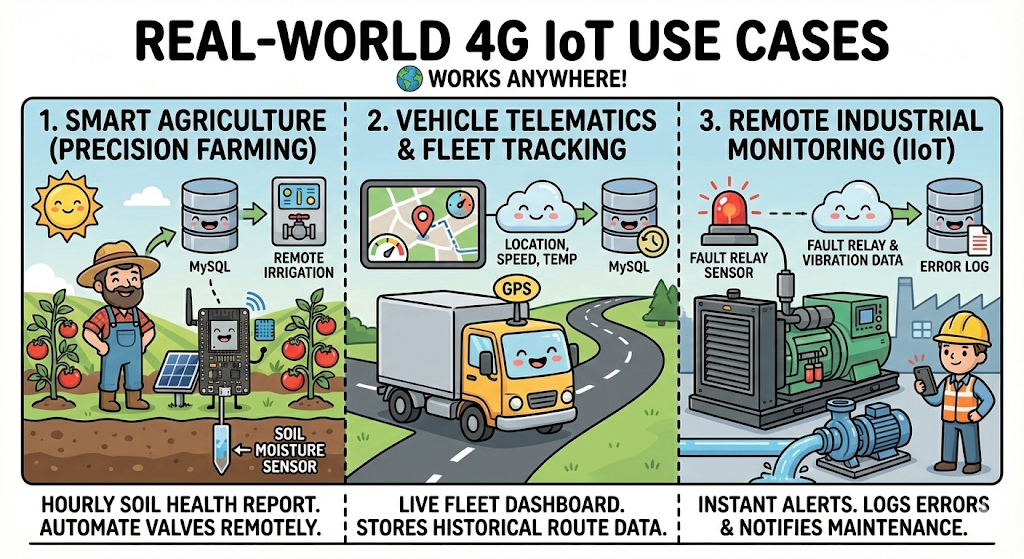
1. Smart Agriculture (Precision Farming)
Farms are often miles from Wi-Fi. By adding a Soil Moisture Sensor and a solar panel, this device can wake up hourly to report soil health to your database. This allows farmers to automate irrigation valves remotely without walking the field.
2. Vehicle Telematics & Fleet Tracking
Logistics companies need to track trucks in real-time. Since the SIM A7670G has built-in GPS, you can modify the code to send location, speed, and engine temperature. This creates a live fleet dashboard that stores historical route data permanently.
3. Remote Industrial Monitoring (IIoT)
Remote generators and water pumps often fail unnoticed. By connecting the ESP32 to a machine’s "Fault" relay or vibration sensor, you get instant alerts. If a machine stops, the system logs the error to MySQL and notifies maintenance engineers immediately.
🚀 Conclusion
Congratulations! You have successfully built a Full-Stack Cellular IoT Solution.
Most beginners stop at blinking an LED or sending data to a local Wi-Fi server. By completing this guide, you have stepped into the world of Professional IoT. You have solved the three biggest challenges in the industry:

- Connectivity: You aren't limited by Wi-Fi range (thanks to 4G LTE).
- Scalability: You aren't relying on public, insecure brokers (thanks to your VPS).
- Data Ownership: You aren't paying a monthly fee to a cloud dashboard (thanks to your own MySQL database).
What's Next? Now that your data is safe in MySQL, the final step is Visualization. In our next tutorial, we will connect Grafana to this MySQL database to create beautiful, real-time dashboards that look like this:
Subscribe to the IoT Bhai YouTube Channel so you don't miss Part 4!