How to Connect SIM800L to Arduino Uno: Fix Power & Network Issues (GSM Bootcamp #1)
Struggling with the SIM800L blinking fast and never connecting? The problem is almost always power. In this first episode of GSM Bootcamp, I show you how to build a robust circuit using a voltage booster and capacitor to ensure your Arduino IoT project gets a stable signal every time.
If you are into IoT, you’ve likely tried using the incredibly cheap SIM800L GSM module. And if you’ve tried using it, you’ve likely pulled your hair out trying to get it to connect to the network.

The module powers on, the LED blinks furiously, and then… nothing. It resets, or just never finds a signal.
The problem is almost always power. The SIM800L is thirsty. While it sips current when idle, it requires massive spikes of up to 2 Amps when searching for a network or transmitting. A standard Arduino 5V pin or a basic USB cable simply cannot provide that burst current fast enough, causing the voltage to drop and the module to reset (a "brownout").
In this first episode of our GSM Bootcamp series, we are going to fix this permanently. We aren't just plugging it in; we are building a robust power supply using a Li-ion battery, a voltage booster, and a capacitor to ensure a stable connection every time.
Let's get started!
Why Use the SIM800L for IoT?
You might be asking, "Why not just use an ESP32 with Wi-Fi?"
While Wi-Fi is great for home automation, it has a major limitation: range. If you are building a project for a farm, a moving vehicle, or a remote weather station, Wi-Fi simply isn't an option. This is where the SIM800L becomes a game changer for IoT engineers.

Here is why this tiny red module is so important:
- True Remote Connectivity: It uses the 2G cellular network (GSM/GPRS), meaning your device can connect to the internet practically anywhere there is a mobile phone signal. You are no longer tethered to a router.
- SMS Capability: Sometimes you don't need a fancy server or a mobile app. With SIM800L, you can trigger relays or get status updates via simple SMS text messages. This is incredibly reliable for critical alerts.
- Cost-Effective: It is one of the cheapest cellular modules on the market. If you need to mass-produce a tracking device or a sensor node, the SIM800L keeps your Bill of Materials (BOM) low compared to expensive 4G or LTE modules.
- Network Redundancy: For critical smart home or industrial projects, you can use the SIM800L as a backup. If the main Wi-Fi goes down, your system can switch to GSM to keep sending data.
In short, mastering the SIM800L unlocks the ability to build "Anywhere IoT" projects.
Watch the Video Tutorial
If you prefer learning visually, I have put together a complete step-by-step video walkthrough of this project.
Required Components (Bill of Materials)
To follow this tutorial, you will need the following hardware:
- Arduino Uno R3 (or compatible board)
- SIM800L GSM Module (with antenna)
- Standard SIM Card (Micro-SIM size, active and unlocked)
- 3.7V Li-ion Battery (18650 cell or similar LiPo battery)
- MT3608 DC-DC Step Up Booster Module (Crucial for stable voltage)
- Electrolytic Capacitor: 470µF or 1000µF (at least 16V rated)
- Resistors for Voltage Divider:
- 1x 1kΩ Resistor
- 1x 2kΩ Resistor
- Breadboard
- Connecting wire
Software Tools
- Arduino IDE: Make sure you have the latest version installed.
Meet the SIM800L Board (Before Any Wiring)
Before connecting a single wire, it’s important to understand what this tiny board actually needs.
The SIM800L is a 2G GSM/GPRS module. It supports:
- SMS
- Voice calls
- GPRS data (TCP/IP, HTTP, MQTT via code)
It does not support 3G or 4G. So make sure 2G is still available in your region.
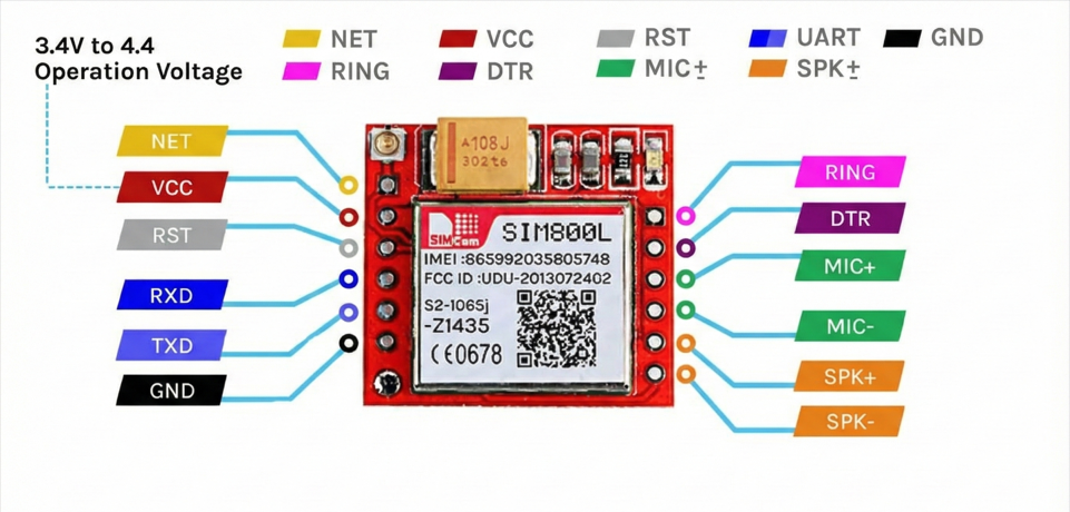
The Red Board usually has pins on both sides.
| Pin | Function | Wiring Note |
| VCC | Power (3.4-4.4V) | Connect to Ext. Power Source (+). |
| GND | Ground | Common Ground with MCU is mandatory. |
| TXD | Transmit | Connect to MCU RX. |
| RXD | Receive | Connect to MCU TX. |
| RST | Reset | Pull LOW to hard reset the module. |
| DTR | Sleep/Wake | Used for power saving (optional). |
| RING | Ring Indicator | Goes LOW on incoming call/SMS (Interrupt). |
Not all pins are required for basic operation. For most projects, VCC, GND, TXD, RXD, and antenna are enough.
Power consumption of SIM800L
| Parameter | Current Consumption |
| Peak Current | 2A (Required during transmission bursts) |
| Call Current | ~216mA (Active voice call) |
| Average Current | ~80mA (Standard operation) |
| Sleep Current | ~0.7mA (Low power mode) |
Power Supply Architecture (The Real Secret)
The SIM800L datasheet says it works at 3.4V – 4.4V (ideal around 4.0V). Many people stop reading right there. That’s the mistake.Voltage is only half the story.
I never found a stable connection with 3.4 to 4.4V. I tried various combinations.
The 2A Burst Problem
When the SIM800L talks to a cell tower — during network attach or data transmission — it pulls short current bursts up to 2A.
Most USB ports, cheap adapters, or onboard regulators can only supply around 500mA.
So what happens?
- The modem pulls 2A
- Voltage drops for a split second
- Brownout occurs
- SIM800L resets itself
Symptom: The LED starts blinking fast, slows down, almost connects… then boom, fast blinking again. Endless loop.
Reliable Power Options
Option A (Best): Li‑Ion Battery (18650) with a step-up module(MT3608)
- Step up voltage range: 4.2V
- High discharge current
- GSM‑friendly by nature
But to be honest, once I accidentally boost the module in 5V and I was surprised that the module works even better than 4.2v, and I got very stable connection.
Option B: Buck Converter (LM2596)
- Step down from 12V or 9V to exactly 4.1V
- Adjust with a multimeter (don’t guess)
The Capacitor Rule (Do Not Skip)
No matter which power source you use:
- Add 470uF Capacitor
- Place it directly across VCC and GND of the SIM800L
This capacitor acts like a tiny energy tank, smoothing those nasty current spikes.
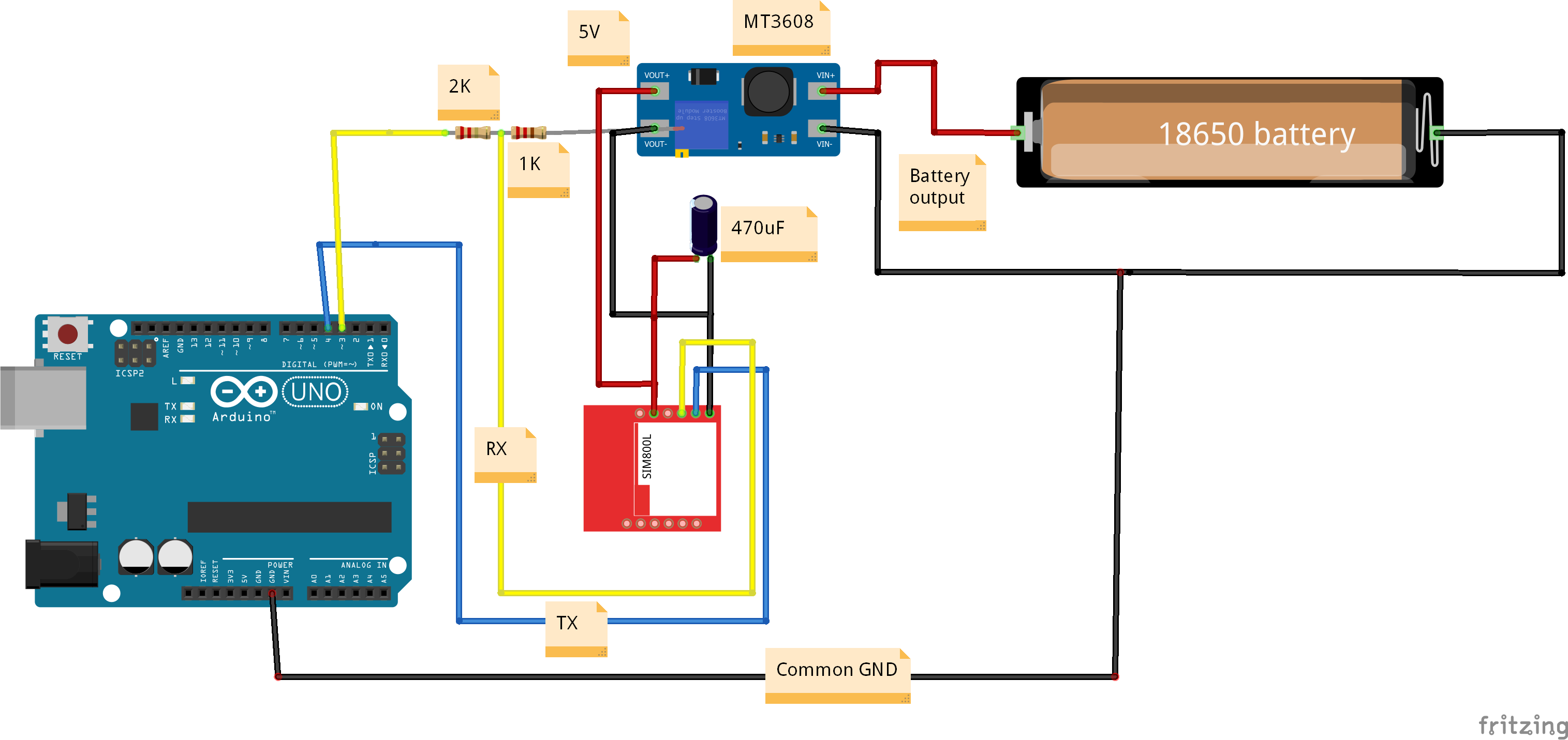
Step 1: Understanding the Circuit Strategy
We are tackling two major issues in this circuit designed by IoT Bhai:
- Power Stability: We will use a 3.7V Li-ion battery, but we need to boost it to a stable level for the SIM800L. We will use an MT3608 booster to step up the battery voltage.
- Logic Level Shifting: The Arduino Uno operates at 5V logic. The SIM800L's RX pin is not 5V tolerant (it prefers about 3.3V). Sending 5V directly can damage the module. We will use a simple voltage divider circuit to protect the SIM800L RX pin.
Step 2: Hardware Connection Guide
Follow these connections carefully. A single misplaced wire, especially related to ground, will prevent this from working.
The Logic & Arduino Connection
- SIM800L VCC - Choose One from the Reliable Power Options
- Common Ground: Connect a wire from the Arduino Uno GND pin to the common ground rail on your breadboard (where the battery negative and SIM800L GND are). If grounds are not connected, nothing will work.
- SIM800L TX Pin: Connect the SIM800L TX pin directly to Arduino Pin 4 (This will be our SoftwareSerial RX). This is safe because the Arduino can read the lower voltage sent by the SIM module.
- SIM800L RX Pin (Voltage Divider): We need to step down the Arduino's 5V signal going to the SIM800L RX.
- Connect Arduino Pin 3 (our SoftwareSerial TX) to one side of the 1kΩ resistor.
- Connect the other side of the 1kΩ resistor to the SIM800L RX pin.
- Also, connect one side of the 2kΩ resistor to the SIM800L RX pin (the same spot as the 1kΩ).
- Connect the other side of the 2kΩ resistor to GND.
Circuit Diagram Visual
Here is the complete wiring diagram used in the experiment:
Step 3: The "Blink Test" (Before Coding)
Before you even upload code, you can verify if your power setup is working.
- Insert your SIM card into the module.
- Power up the system (connect the battery to the booster).
- Watch the red LED on the SIM800L module.
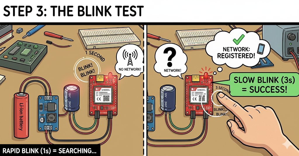
Diagnosis:
- Blinking rapidly (every 1 second): The module is powered on but is frantically searching for a network. It has not connected yet.
- Blinking slowly (once every 3 seconds): Success! The module has found a network and is registered. Your hardware setup is solid.
If it stays blinking rapidly for more than a minute, re-check your capacitor and your power connections.
Step 4: Software Setup
We will use the excellent TinyGSM library to manage the complex AT commands in the background.
- Open Arduino IDE.
- Go to Sketch -> Include Library -> Manage Libraries...
- Search for "TinyGSM" and install the library by Volodymyr Shymanskyy.
Now, copy and paste the following test code. This code initializes the modem and, once connected, prints out the signal quality and operator name every 5 seconds.
/**************************************************************
 *
 * TinyGSM Getting Started for SIM800L and Arduino Uno
 * By IoT Bhai
 *
 **************************************************************/

// Select your modem:
#define TINY_GSM_MODEM_SIM800

// Set serial for debug console (to the Serial Monitor)
#define SerialMon Serial

// Set serial for AT commands (to the SIM800L module)
#include <SoftwareSerial.h>
// RX pin (Arduino pin 4) goes to SIM800L TX
// TX pin (Arduino pin 3) goes to SIM800L RX (via voltage divider!)
SoftwareSerial SerialAT(4, 3);

#define TINY_GSM_DEBUG SerialMon

#include <TinyGSM.h>

// Your GPRS credentials, if any (leave blank for many carriers)
const char apn[]  = "YourAPN";
const char user[] = "";
const char pass[] = "";

TinyGsm modem(SerialAT);

void setup() {
  // Set console baud rate
  SerialMon.begin(115200);
  delay(10);

  // Set GSM module baud rate
  // Keep it at 9600 for stable SoftwareSerial communication
  SerialAT.begin(9600);
  delay(3000);

  SerialMon.println("Initializing modem...");
  modem.restart();

  String modemInfo = modem.getModemInfo();
  SerialMon.print("Modem Info: ");
  SerialMon.println(modemInfo);

  SerialMon.print("Waiting for network...");
  if (!modem.waitForNetwork()) {
    SerialMon.println(" fail");
    delay(10000);
    return;
  }
  SerialMon.println(" success");

  if (modem.isNetworkConnected()) {
    SerialMon.println("Network connected");
  }

  // GPRS connection parameters are usually set after network registration
  /*
  SerialMon.print(F("Connecting to "));
  SerialMon.print(apn);
  if (!modem.gprsConnect(apn, user, pass)) {
    SerialMon.println(" fail");
    delay(10000);
    return;
  }
  SerialMon.println(" success");

  if (modem.isGprsConnected()) {
    SerialMon.println("GPRS connected");
  }
  */
}

void loop() {
  // In the loop, we will periodically check signal strength

  int csq = modem.getSignalQuality();
  SerialMon.print("Signal Quality: ");
  SerialMon.println(csq);
  // CSQ ranges from 0-31. Higher is better.
  // Anything above 15 is generally decent. 20+ is great.

  String operatorName = modem.getOperator();
  SerialMon.print("Operator: ");
  SerialMon.println(operatorName);

  SerialMon.println("-------------------");
  delay(5000); // Wait 5 seconds before checking again
}
Step 5: Testing the Output
- Connect your Arduino Uno to your PC via USB.
- Select the correct Board and Port in the Arduino IDE.
- Upload the code.
- Open the Serial Monitor.
- Make sure the baud rate is set to 115200.
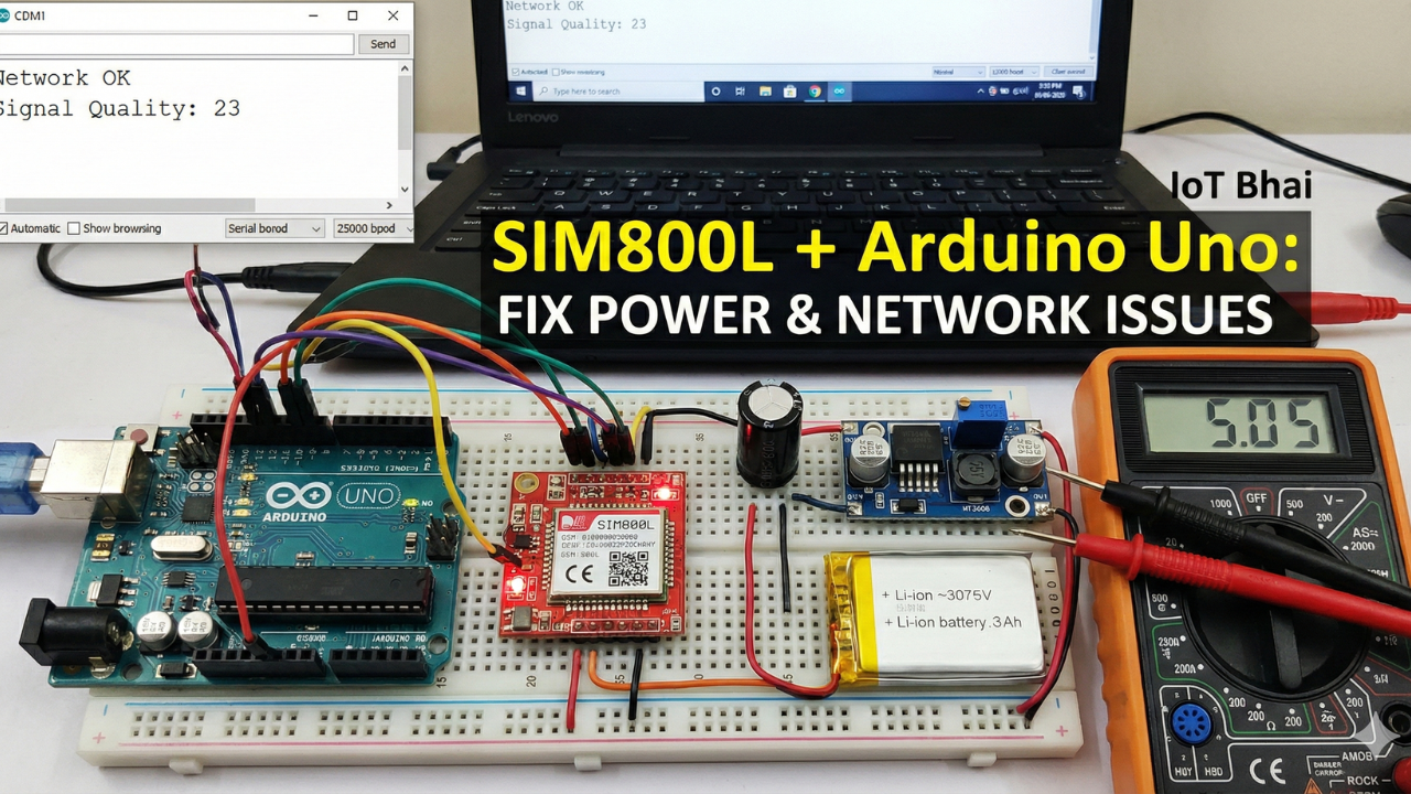
You should see the modem initialize, find the network, and then start reporting signal quality (CSQ). A CSQ over 15 is usually acceptable for reliable data transmission. Our test showed a strong signal of around 23.
What’s Actually Happening
We use the TinyGSM library to avoid dealing with raw AT commands directly.But knowing what happens underneath makes debugging 10x easier.
Modem Initialization
When you call: modem.restart();
TinyGSM sends something like:
AT→ check if modem respondsAT+CFUN=1,1→ full modem reset
If your code gets stuck here, communication is already broken.
Network Registration
modem.waitForNetwork();
Under the hood, this repeatedly sends:
AT+CREG?
Responses:
0,1→ Registered (home network)0,5→ Registered (roaming)0,2→ Searching0,0→ Not registered
If it keeps searching forever, the problem is not TinyGSM.
Signal Quality (CSQ)
modem.getSignalQuality();
This sends:
AT+CSQ
Interpretation:
- 0–9 → Very weak (likely to fail)
- 10–14 → OK for SMS
- 15–19 → Good for GPRS
- 20–30 → Excellent
If CSQ is low, don’t expect miracles.
Advanced Troubleshooting (Real‑World Cases)
Scenario A: Stuck on “Initializing modem…”
Cause: ESP32 is not receiving data.
Fix:
- Swap TX and RX
- Check if LED is blinking (power issue?)
- Start with baud rate 9600
Scenario B: Continuous Resets
Cause: Power brownout during radio activity.
Fix:
- Shorten power wires (thin, long wires = voltage drop)
Scenario C: Network Fail After Timeout
Cause: Modem works, network rejects it.
Fix:
- Check antenna placement (don’t touch metal)
- Make sure SIM is active
- Check Voltage
- Disable SIM PIN lock (test in a phone)
- Fully power off the module and retry
Check the Status LED
- Fast blinking (about 5–6 times per second)
The module is powered ON but not registered to any network yet. This usually means it is still searching, or failed to attach. - Blink every 1 second
Network search is in progress. If it stays here for more than a minute, check antenna and SIM status. - Blink every 2 seconds
Registered on the network, but data session is not active yet. This is a good sign. - Blink every 3 seconds
Successfully registered and idle. The modem is ready for SMS, calls, or GPRS. - Very rapid or irregular blinking
Active data transmission (GPRS) or incoming activity. - LED OFF
Power issue, shutdown, or PWRKEY not asserted correctly.
Still Not Connected. Check our troubleshooting SIM800L blog.
Conclusion
You have successfully built a stable hardware foundation for your GSM projects! By using a dedicated battery, a voltage booster, and a capacitor, you have eliminated the most common cause of SIM800L failures.

Stay tuned for GSM Bootcamp #2, where we will take this setup and learn how to send and receive SMS messages using the Arduino.