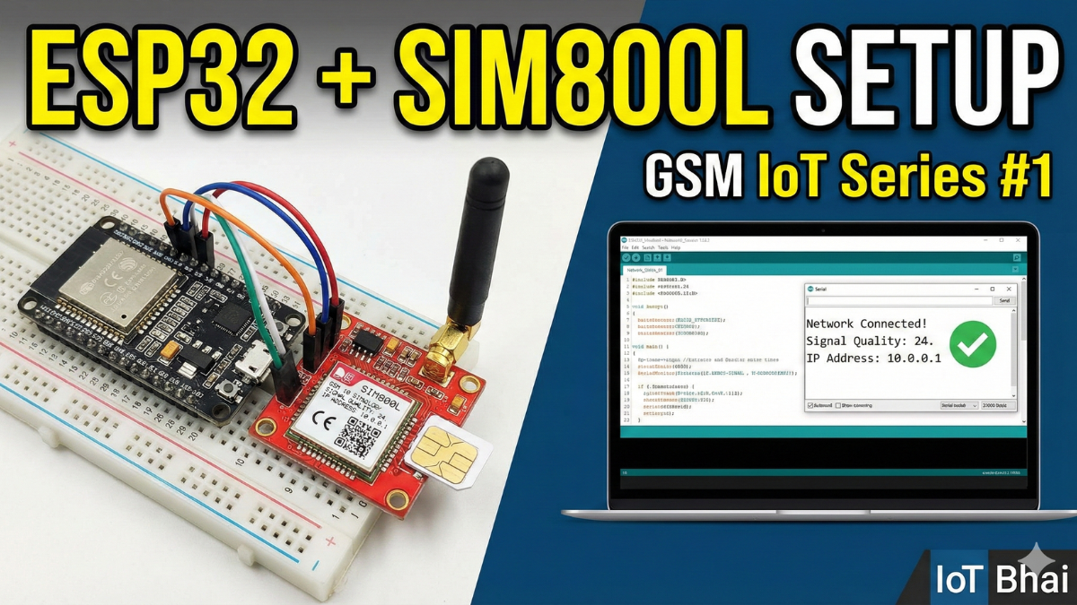
How to Connect SIM800L to ESP32 | GSM Setup & Network Test (GSM IoT Series #1)
If you’ve ever connected a SIM800L to an ESP32 and thought, “Why does this thing reset the moment it finds a network?” — welcome.
On paper, GSM modules are simple. In reality, the SIM800L is one of the most misunderstood modules in IoT. Most failures don’t come from code. They come from power, wiring, and timing.
Connecting a GSM module to a microcontroller sounds simple:
TX to RX, power it up, send AT commands.
In reality, the SIM800L is notorious for random resets, network failures,
and “it worked yesterday” bugs.
In Part 1 of the GSM IoT Projects series, we’ll focus on one thing only:
building a stable ESP32 + SIM800L connection — the way it’s done in real projects.
What This Guide Covers
- SIM800L board overview and pinout
- Power consumption (active, idle, burst current)
- Antenna basics and common mistakes
- Proper power supply design (the real secret)
- Reliable UART wiring with ESP32
- What TinyGSM actually does behind the scenes
- How to debug issues before you blame the code
Watch the Video Tutorial
If you prefer learning visually, I have put together a complete step-by-step video walkthrough of this project.
Required Component
Hardware
- SIM800L Module with the Header and Antenna soldered
- ESP32 Development Board
- Micro SIM Card (With Credit)
- Battery(Optional)
- DC-DC Booster Module (MT3608 or similar) if you use a Battery(Optional)
- 470 uF 25V Capacitor
- Breadboard
- Connecting wire
- MicroUSB Cable
Software Tools
- Arduino IDE: Make sure you have the latest version installed.
- ESP32 Board Support: You must have the ESP32 board manager installed in your IDE. Need help? Check out my guide: How to Set Up ESP32 in Arduino IDE 2.0 (Windows/Ubuntu)
Meet the SIM800L Board (Before Any Wiring)
Before connecting a single wire, it’s important to understand what this tiny board actually needs.
The SIM800L is a 2G GSM/GPRS module. It supports:
- SMS
- Voice calls
- GPRS data (TCP/IP, HTTP, MQTT via code)
It does not support 3G or 4G. So make sure 2G is still available in your region.
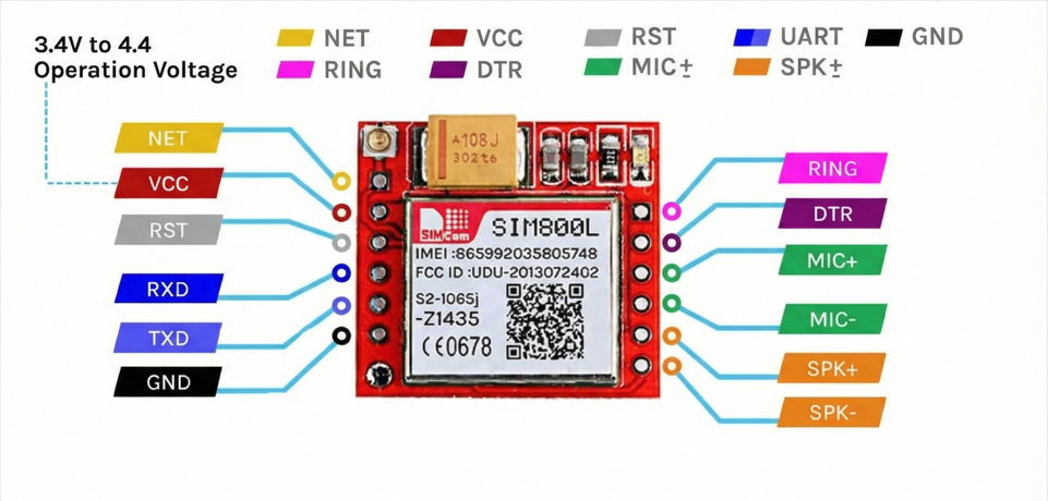
Depending on the breakout board, pin labels may vary slightly, but the core pins are the same:
The Red Board usually has pins on both sides.
| Pin | Function | Wiring Note |
| VCC | Power (3.4-4.4V) | Connect to Ext. Power Source (+). |
| GND | Ground | Common Ground with MCU is mandatory. |
| TXD | Transmit | Connect to MCU RX. |
| RXD | Receive | Connect to MCU TX. |
| RST | Reset | Pull LOW to hard reset the module. |
| DTR | Sleep/Wake | Used for power saving (optional). |
| RING | Ring Indicator | Goes LOW on incoming call/SMS (Interrupt). |
Not all pins are required for basic operation. For most projects, VCC, GND, TXD, RXD, and antenna are enough.
Power consumption of SIM800L
| Parameter | Current Consumption |
| Peak Current | 2A (Required during transmission bursts) |
| Call Current | ~216mA (Active voice call) |
| Average Current | ~80mA (Standard operation) |
| Sleep Current | ~0.7mA (Low power mode) |
The onboard LED tells you the network status.
| Blink Pattern | Status |
| Fast Blink (1 sec) | Searching for network / Not registered. |
| Slow Blink (3 sec) | Registered (Connected and ready). |
| Double Blink | GPRS Data is active. |
| No Light | Power failure or Defective unit. |
Antenna: Small Part, Big Impact
The SIM800L antenna connector is IPEX (very small).

Common mistakes:
- Running the module without antenna
- Letting the antenna touch metal or ground planes
- Using very cheap coil antennas and expecting miracles
Rules:
- Always connect the antenna before powering the module
- Keep antenna away from metal
- Don’t coil or crush the cable
Bad antenna = weak CSQ = failed network attach.
Power Supply Architecture (The Real Secret)
The SIM800L datasheet says it works at 3.4V – 4.4V (ideal around 4.0V). Many people stop reading right there. That’s the mistake.Voltage is only half the story.
I never found a stable connection with 3.4 to 4.4V. I tried various combinations.
The 2A Burst Problem
When the SIM800L talks to a cell tower — during network attach or data transmission — it pulls short current bursts up to 2A.
Most USB ports, cheap adapters, or onboard regulators can only supply around 500mA.
So what happens?
- The modem pulls 2A
- Voltage drops for a split second
- Brownout occurs
- SIM800L resets itself
Symptom: The LED starts blinking fast, slows down, almost connects… then boom, fast blinking again. Endless loop.
Reliable Power Options
Option A (Best): Li‑Ion Battery (18650) with a step-up module(MT3608)
- Step up voltage range: 4.2V
- High discharge current
- GSM‑friendly by nature
But to be honest, once I accidentally boost the module in 5V and I was surprised that the module works even better than 4.2v, and I got very stable connection.
Option B: Buck Converter (LM2596)
- Step down from 12V or 9V to exactly 4.1V
- Adjust with a multimeter (don’t guess)
The Capacitor Rule (Do Not Skip)
No matter which power source you use:
- Add 470uF Capacitor
- Place it directly across VCC and GND of the SIM800L
This capacitor acts like a tiny energy tank, smoothing those nasty current spikes.
Hardware Connection
ESP32 uses 3.3V logic. SIM800L is technically 2.8V logic, but in practice it’s usually 3.3V tolerant.
I’ve been running it directly without a level shifter and it works fine (still, do it at your own risk).
Why Hardware Serial Matters
Unlike Arduino Uno (which often uses SoftwareSerial), ESP32 gives us multiple hardware UARTs.
- UART0 → USB programming & Serial Monitor
- UART2 → Free and perfect for GSM
We use UART2 for SIM800L. This keeps communication stable and avoids CPU timing issues.
Pin Mapping
- ESP32 TX (GPIO 26) → SIM800L RX
- ESP32 RX (GPIO 27) → SIM800L TX
- SIM800L VCC - Choose One from the Reliable Power Options
Common Ground (Very Important)
You must connect:
- ESP32 GND
- SIM800L GND
- Power supply GND
If grounds are not common, serial data levels float and nothing works. No error, just silence.
Circuit Diagram
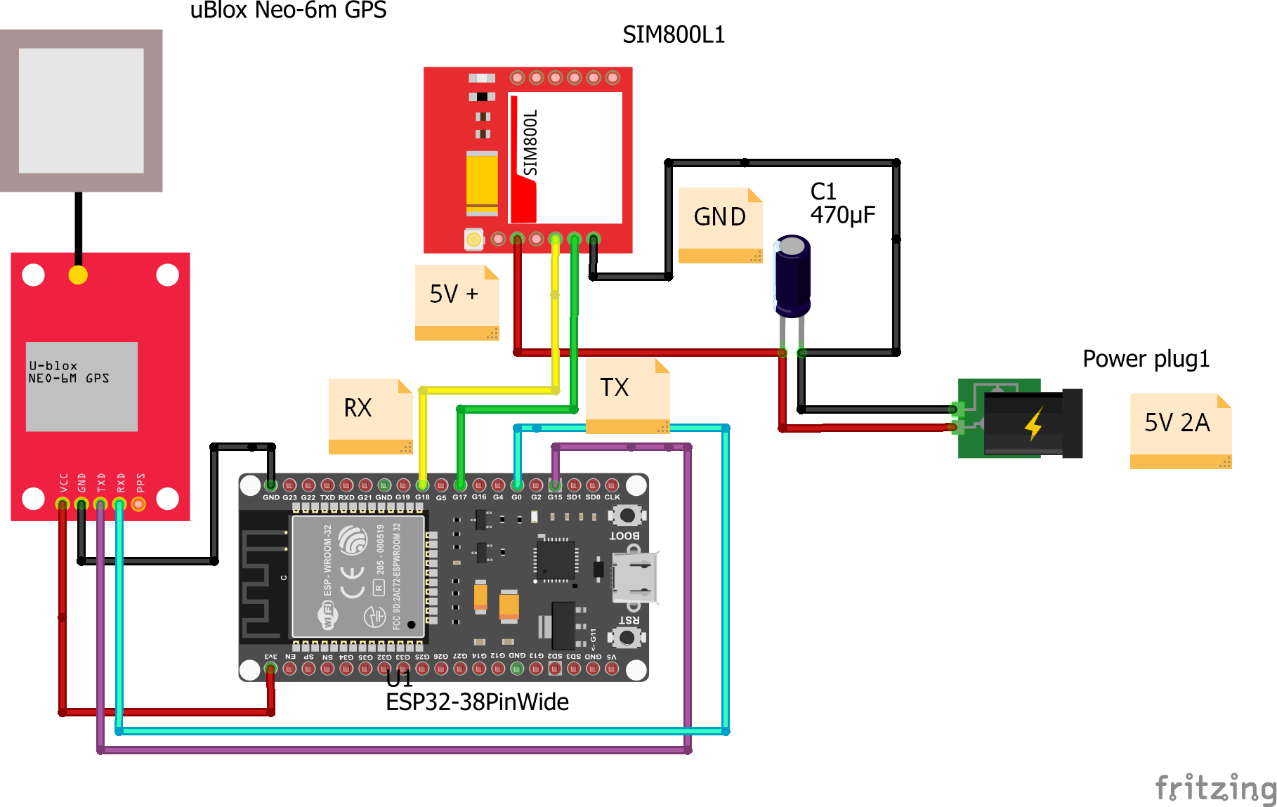
I use 5V here, and I got a very stable connection even datasheet says the maximum is 4.4V. You can try with 4.2v first, if it works then great. If it doesn't work, you can try with 5V.
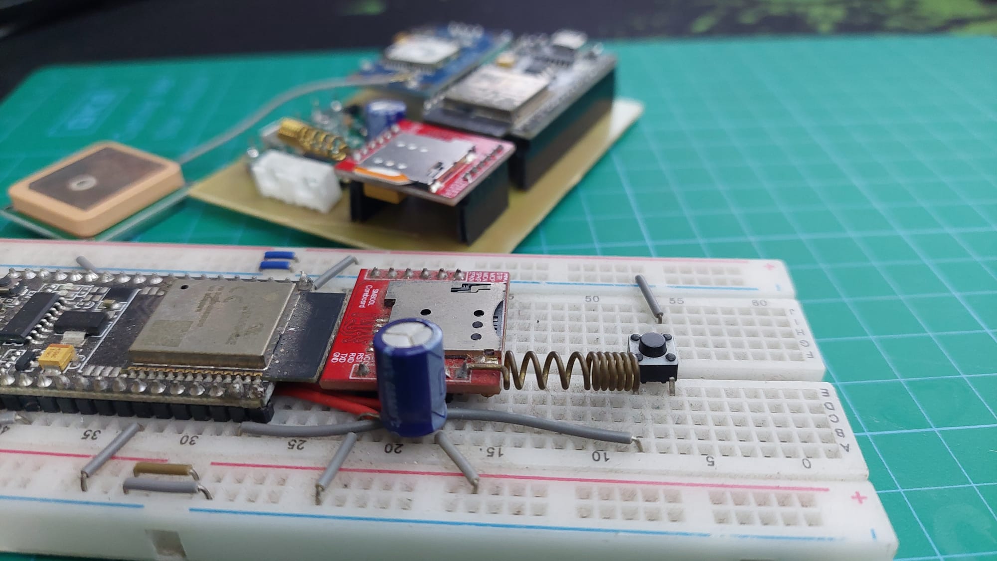
My Circuit
The Code
Install TinyGSM Library From Arduino Serial Monitor
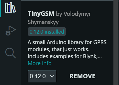
Github Link

Code
#define TINY_GSM_MODEM_SIM800
#define SerialMon Serial
#define SerialAT Serial1
#define TINY_GSM_DEBUG SerialMon
#define GSM_PIN ""
#define NTP_SERVER "132.163.96.5"
#include <TinyGsmClient.h>
const char apn[] = "internet";
const char gprsUser[] = "";
const char gprsPass[] = "";
#ifdef DUMP_AT_COMMANDS
#include <StreamDebugger.h>
StreamDebugger debugger(SerialAT, SerialMon);
TinyGsm modem(debugger);
#else
TinyGsm modem(SerialAT);
#endif
TinyGsmClient client(modem);
// ESP32 and SIM800l pins
#define MODEM_TX 26 // mandatory pin
#define MODEM_RX 27 // mandatory pin
#define MODEM_RST 14 // optional
#define MODEM_DTR 25 // optional
#define MODEM_RING 34 // optional
void setup() {
SerialMon.begin(115200);
delay(1000);
pinMode(MODEM_RST, OUTPUT);
digitalWrite(MODEM_RST, LOW);
delay(100); // Keep low for 100ms
digitalWrite(MODEM_RST, HIGH); // Release reset pin
delay(1000); // Wait for module to boot
pinMode(MODEM_DTR, OUTPUT);
digitalWrite(MODEM_DTR, HIGH); // Keep modem awake
pinMode(MODEM_RING, INPUT); // Optional
SerialMon.println("Wait ...");
SerialAT.begin(115200, SERIAL_8N1, MODEM_TX, MODEM_RX);
delay(3000);
SerialMon.println("Initializing modem ...");
modem.init();
String modemInfo = modem.getModemInfo();
SerialMon.print("Modem Info: ");
SerialMon.println(modemInfo);
if (GSM_PIN && modem.getSimStatus() != 3) {
modem.simUnlock(GSM_PIN);
}
SerialMon.print("Waiting for network...");
if (!modem.waitForNetwork()) {
SerialMon.println(" fail");
delay(10000);
return;
}
SerialMon.println(" success");
if (modem.isNetworkConnected()) {
DBG("Network connected");
}
// IMEI
String imei = modem.getIMEI();
SerialMon.print("IMEI: ");
SerialMon.println(imei);
// Get operator name
String operatorName = modem.getOperator();
SerialMon.print("Operator: ");
SerialMon.println(operatorName);
// Signal quality (0–31, 99 = not known)
int signalQuality = modem.getSignalQuality();
SerialMon.print("Signal Quality (0-31): ");
SerialMon.println(signalQuality);
SerialMon.print("Connecting to APN: ");
SerialMon.print(apn);
if (!modem.gprsConnect(apn, gprsUser, gprsPass)) {
SerialMon.println(" fail");
ESP.restart();
}
SerialMon.println(" OK");
if (modem.isGprsConnected()) {
SerialMon.println("GPRS connected");
}
// Local IP
IPAddress localIP = modem.localIP();
SerialMon.print("Local IP: ");
SerialMon.println(localIP);
}
void loop() {
static unsigned long lastPrint = 0;
if (millis() - lastPrint > 5000) { // every 5 seconds
int signal = modem.getSignalQuality();
SerialMon.print("Signal Quality (0-31): ");
SerialMon.println(signal);
// Optional: Check if still connected
if (!modem.isNetworkConnected()) {
SerialMon.println("Network disconnected!");
} else {
SerialMon.println("Network OK");
}
lastPrint = millis();
}
delay(100);
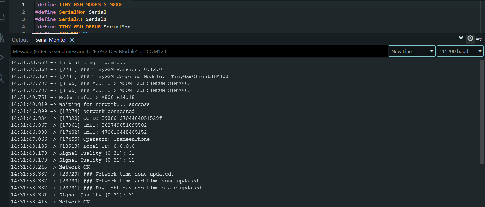
}Arduino Serial Monitor Output
If your Arduino serial monitor is giving this, then your SIM800L is successfully connected to the Network
What’s Actually Happening
We use the TinyGSM library to avoid dealing with raw AT commands directly.
But knowing what happens underneath makes debugging 10x easier.
Modem Initialization
When you call:
modem.restart();
TinyGSM sends something like:
AT→ check if modem respondsAT+CFUN=1,1→ full modem reset
If your code gets stuck here, communication is already broken.
Network Registration
modem.waitForNetwork();
Under the hood, this repeatedly sends:
AT+CREG?
Responses:
0,1→ Registered (home network)0,5→ Registered (roaming)0,2→ Searching0,0→ Not registered
If it keeps searching forever, the problem is not TinyGSM.
Signal Quality (CSQ)
modem.getSignalQuality();
This sends:
AT+CSQ
Interpretation:
- 0–9 → Very weak (likely to fail)
- 10–14 → OK for SMS
- 15–19 → Good for GPRS
- 20–30 → Excellent
If CSQ is low, don’t expect miracles.
Advanced Troubleshooting (Real‑World Cases)
Scenario A: Stuck on “Initializing modem…”
Cause: ESP32 is not receiving data.
Fix:
- Swap TX and RX
- Check if LED is blinking (power issue?)
- Start with baud rate 9600
Scenario B: Continuous Resets
Cause: Power brownout during radio activity.
Fix:
- Shorten power wires (thin, long wires = voltage drop)
Scenario C: Network Fail After Timeout
Cause: Modem works, network rejects it.
Fix:
- Check antenna placement (don’t touch metal)
- Make sure SIM is active
- Check Voltage
- Disable SIM PIN lock (test in a phone)
- Fully power off the module and retry
Check the Status LED
- Fast blinking (about 5–6 times per second)
The module is powered ON but not registered to any network yet. This usually means it is still searching, or failed to attach. - Blink every 1 second
Network search is in progress. If it stays here for more than a minute, check antenna and SIM status. - Blink every 2 seconds
Registered on the network, but data session is not active yet. This is a good sign. - Blink every 3 seconds
Successfully registered and idle. The modem is ready for SMS, calls, or GPRS. - Very rapid or irregular blinking
Active data transmission (GPRS) or incoming activity. - LED OFF
Power issue, shutdown, or PWRKEY not asserted correctly.
Final Thoughts (For Part 1)
If your SIM800L is unstable, don’t touch the code first.
Fix power. Fix wiring. Fix grounding.
Once those are solid, GSM suddenly feels… boring. And boring is good in IoT.
In Part 2, we’ll cover:
Get the hardware right, and everything else becomes predictable.
See you in the next part ✌️
Feel Free to comment.