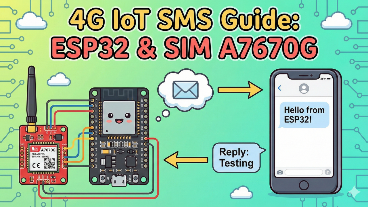
How to Send & Receive SMS with ESP32 and SIM A7670G (4G LTE)
In Part 2 of our 4G IoT series, we move beyond hardware setup to real communication. Learn how to write code to automatically send text messages from your ESP32 and listen for incoming SMS commands using the SIM A7670G LTE module. Perfect for remote control projects!
Welcome back to the IoT Bhai 4G series!
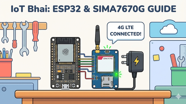
In our previous guide, Connect SIM A7670G with ESP32: 4G LTE IoT Guide, we covered the fundamentals: how to wire the module, the critical importance of a stable power supply, and how to get your first network connection.
If you haven't set up your hardware yet, please read that guide first. The A7670G is power-hungry and has specific wiring requirements that differ from older 2G modules.
Today, we are taking the next step: Communication.
We will write code to:
- Send an SMS from the ESP32 to your smartphone automatically.
- Receive SMS commands from your phone and display them on the ESP32.
This is the foundation for projects like SMS-controlled relays, emergency alert systems, and remote data loggers where Wi-Fi isn't available.
Watch the Video Tutorial
If you prefer learning visually, I have put together a complete step-by-step video walkthrough of this project.
Prerequisites: The Hardware Checklist
Before we begin, ensure you have the following components ready:
- ESP32 Development Board (e.g., DOIT DevKit V1 or similar).
- SIM A7670G Breakout Board (Ensure it comes with the LTE and GPS antennas).
- A Nano SIM Card with an active 4G data plan.
- Jumper Wires (Female-to-Male or Female-to-Female depending on your board headers).
- CRITICAL: A Stable External Power Supply (Rated 5V, capable of delivering at least 2.5A current).
- Micro USB Cable (optional), if you want to power the sim module via usb port
The Hardware Setup
The wiring remains the same as Part 1. If you have not wired your module yet, or if you are unsure about the power requirements, please refer to our detailed setup guide here:
👉Read Part 1: Connect SIM A7670G with ESP32 - Hardware & Wiring Guide
⚠️ Important: Ensure your SIM module is powered by an external 5V 2A power source, not the ESP32.
Software:
- Arduino IDE: Make sure you have the latest version installed.
- ESP32 Board Support: You must have the ESP32 board manager installed in your IDE. Need help? Check out my guide: How to Set Up ESP32 in Arduino IDE 2.0 (Windows/Ubuntu)
Software Setup (The TinyGSM Library)
To communicate with the modem using AT commands without writing complex parsing code, we rely on the TinyGSM library.
⚠️ Crucial Library Warning
The standard version of TinyGSM found in the Arduino Library Manager may not fully support the A7670G's specific AT command set yet.
For this tutorial to work, you must use the specific fork linked below:
- Download Library: https://github.com/lewisxhe/TinyGSM-fork
Installation Instructions:
- Download the repository as a
.zipfile from GitHub. - Open Arduino IDE.
- Go to Sketch -> Include Library -> Add .ZIP Library...
- Select the downloaded file.
The Code
- Make sure you have installed the TinyGSM library (use the specific fork mentioned in the video description if the standard one fails).
- Change
ADMIN_NUMBERto your personal phone number (include the country code, e.g., +880...).
#define TINY_GSM_MODEM_A7670
#define SerialMon Serial
#define SerialAT Serial1
#define TINY_GSM_DEBUG SerialMon
#define GSM_PIN ""

#include <TinyGsmClient.h>

#define ADMIN_NUMBER "" // put your number with country code

// === SIM7600 Pin Definitions ===
#define MODEM_RESET_PIN 5
#define MODEM_PWKEY 4
#define MODEM_POWER_ON 12
#define MODEM_TX 26
#define MODEM_RX 27
#define MODEM_RESET_LEVEL HIGH

#ifdef DUMP_AT_COMMANDS
#include <StreamDebugger.h>
StreamDebugger debugger(SerialAT, Serial);
TinyGsm modem(debugger);
#else
TinyGsm modem(SerialAT);
#endif

String phoneNumber = "";
String text = "";

void setup() {
  SerialMon.begin(115200);
  // Power ON the modem
  pinMode(MODEM_POWER_ON, OUTPUT);
  digitalWrite(MODEM_POWER_ON, HIGH);

  // Hardware reset
  pinMode(MODEM_RESET_PIN, OUTPUT);
  digitalWrite(MODEM_RESET_PIN, !MODEM_RESET_LEVEL);
  delay(100);
  digitalWrite(MODEM_RESET_PIN, MODEM_RESET_LEVEL);
  delay(2600);
  digitalWrite(MODEM_RESET_PIN, !MODEM_RESET_LEVEL);

  // Toggle PWRKEY to power up the modem
  pinMode(MODEM_PWKEY, OUTPUT);
  digitalWrite(MODEM_PWKEY, LOW);
  delay(100);
  digitalWrite(MODEM_PWKEY, HIGH);
  delay(1000);
  digitalWrite(MODEM_PWKEY, LOW);

  SerialMon.println("Wait ...");
  SerialAT.begin(115200, SERIAL_8N1, MODEM_RX, MODEM_TX);
  delay(3000);

  SerialMon.println("Initializing modem...");
  if (!modem.init()) {
    SerialMon.println("Failed to restart modem, delaying 10s and retrying");
    delay(10000);
    return;
  }
  Serial.println("Wait SMS Done.");
  if (!modem.waitResponse(100000UL, "SMS DONE")) {
    Serial.println("Can't wait from sms register ....");
    return;
  }
  String modemInfo = modem.getModemInfo();
  SerialMon.print("Modem Info: ");
  SerialMon.println(modemInfo);
  // Unlock SIM if needed
  if (GSM_PIN && modem.getSimStatus() != 3) {
    modem.simUnlock(GSM_PIN);
  }
  SerialMon.print("Waiting for network...");
  if (!modem.waitForNetwork()) {
    SerialMon.println(" fail");
    delay(10000);
    return;
  }
  SerialMon.println(" success");
  if (modem.isNetworkConnected()) {
    SerialMon.println("Network connected");
  }

  String imei = modem.getIMEI();
  Serial.print("Init success, start to send message to  ");
  Serial.println(ADMIN_NUMBER);
  bool res = modem.sendSMS(ADMIN_NUMBER, String("Hello from ") + imei);
  Serial.print("Send sms message ");
  Serial.println(res ? "OK" : "fail");

  // Enable SMS text mode and notifications
  SerialAT.print("AT+CMGF=1\r");
  delay(1000);
  SerialAT.print("AT+CNMI=2,2,0,0,0\r");
  delay(1000);
}

void loop() {
  while (SerialAT.available()) {
    String response = SerialAT.readStringUntil('\n');
    Serial.println(response);
    // Incoming SMS
    if (response.startsWith("+CMT: ")) {
      int firstQuotePos = response.indexOf("+CMT: ") + 7;
      int secondQuotePos = response.indexOf("\"", firstQuotePos);
      phoneNumber = response.substring(firstQuotePos, secondQuotePos);
      Serial.print("Phone Number: ");
      Serial.println(phoneNumber);
    }
  }
}
Testing & Results
- Upload the Code: Connect your ESP32 to the PC and upload the sketch.
- Open Serial Monitor: Set baud rate to 115200.
- Observation:
- You will see the "Wait..." message while the code toggles the pins to boot the modem.
- Once initialized, it will print
Modem Info: SIMCOM_Ltd A7670G. - It will wait for the network (this can take 10-20 seconds).
- Upon success, you will see
GPRS connectedfollowed by a loop printing the Signal Quality (0-31) and Operator name.
Expected output
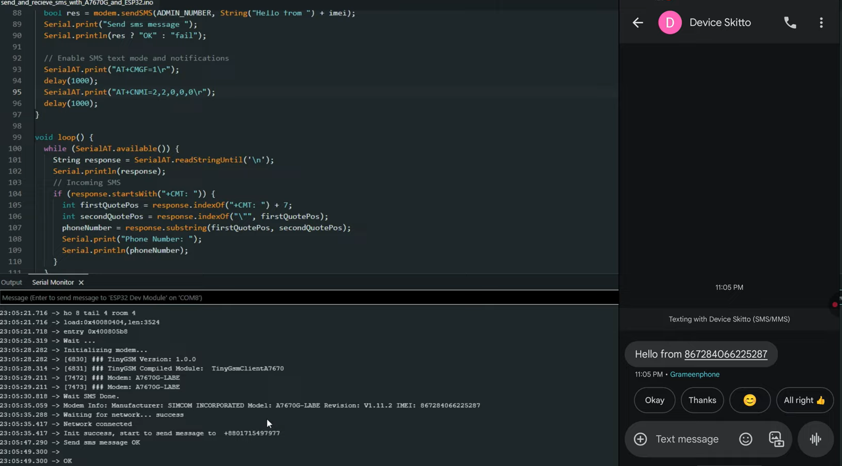
Watch the output
The Code Logic Explained
Before you copy-paste the code, it is important to understand how it works, specifically the "Receiving" part, which handles data differently than standard examples.
1. The Startup Sequence
The A7670G is a powerful industrial module. It needs a specific "kick" to wake up. In setup(), we toggle the RESET and PWRKEY pins in a specific timing sequence (High -> Low -> High) to ensure the modem boots up correctly every time the ESP32 restarts.
2. Waiting for "SMS DONE"
After the modem boots, it loads its firmware. We cannot send an SMS immediately. The code waits for a specific message from the modem called "SMS DONE".
if (!modem.waitResponse(100000UL, "SMS DONE")) { ... }
If we try to send a text before this flag appears, the message will fail.
3. Real-Time Receiving (The CNMI Command)
Instead of constantly asking the modem "Do I have new messages?", we tell the modem to push messages to us instantly. We do this with:
SerialAT.print("AT+CMGF=1\r"); // Set to Text Mode
SerialAT.print("AT+CNMI=2,2,0,0,0\r"); // Route new SMS directly to Serial
This command tells the A7670G: "Don't save new messages to the SIM card. Send them directly to the ESP32 immediately."
This is why inside the loop(), we manually read the SerialAT stream to find the phone number and message text.
Real-World Use Cases
Why would you use SMS when this module has 4G Internet? Here are 4 practical scenarios where SMS is the superior choice:
- Smart Agriculture (Pump Control): In remote fields where data coverage is spotty, SMS is often more reliable. You can program the ESP32 to turn irrigation pumps ON or OFF simply by texting "PUMP_ON" from your phone.
- Security & Intrusion Alerts: Build a security system for a remote cabin or warehouse. If a door sensor is triggered, the ESP32 can instantly text you an alert, ensuring you know immediately even without an internet dashboard.
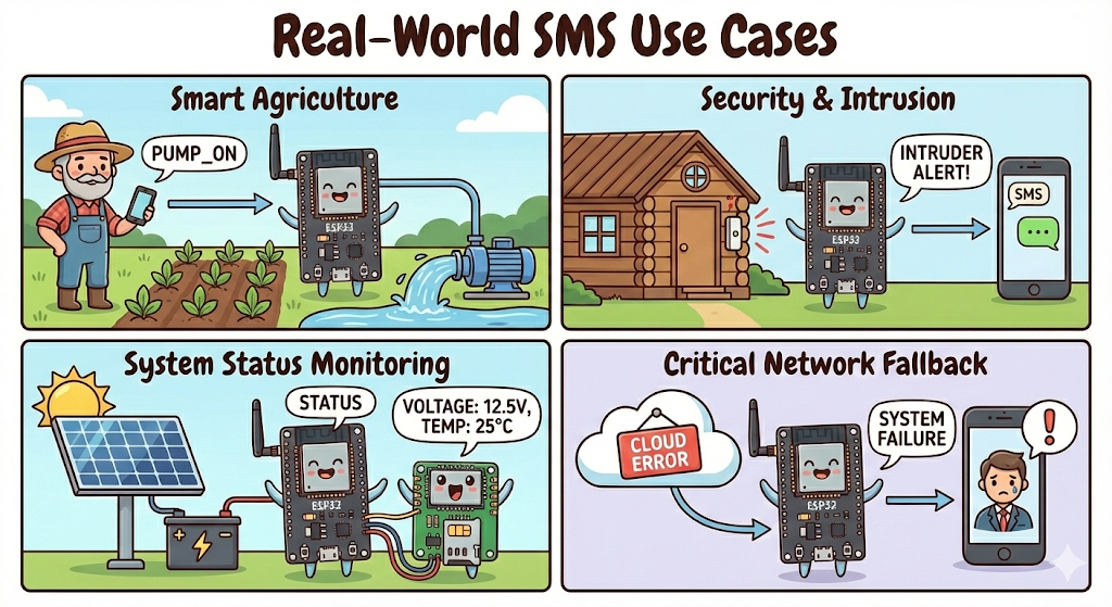
- System Status Monitoring: Not sure if your solar battery is charged? You can program the device to reply to a "STATUS" text with current voltage, temperature, and uptime statistics.
- Critical Network Fallback: If you are building a commercial product, what happens if your MQTT broker goes down? You can use SMS as a "fail-safe" backup channel to notify administrators of a system failure.
Conclusion & What's Next
Congratulations! You have successfully upgraded your ESP32 project with two-way cellular text messaging. You are now able to control your device remotely and receive status updates from anywhere in the world, without relying on Wi-Fi.
This SMS capability is perfect for alerts and simple commands, but for real-time data logging and complex dashboards, we need internet connectivity.
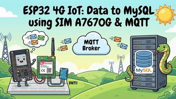
In the next tutorial (Part 3), we will unlock the full potential of the A7670G.
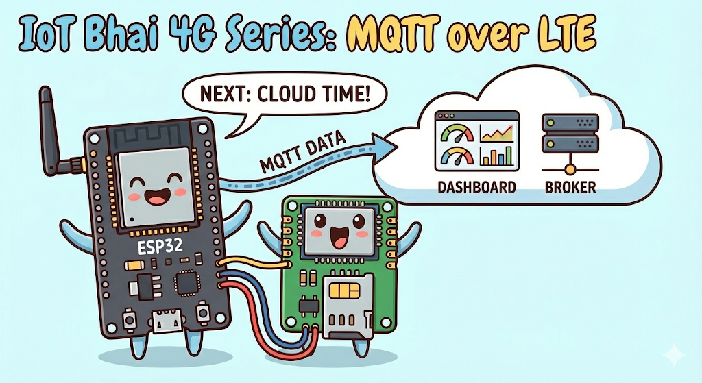
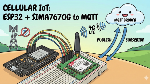
We will enable the data connection (GPRS/LTE) to connect the ESP32 to an MQTT Broker over 4G. You will learn how to:
- Activate the data context on the SIM.
- Publish sensor data to the cloud via MQTT.
- Subscribe to topics to control your device in real-time from a dashboard.
Stay tuned, because that is where the real IoT magic happens!
Don't miss the next update—subscribe to IoT Bhai on YouTube and hit the notification bell!