How to Connect MQTT using SIM800L GSM Module and ESP32 (GSM IoT Series #5)
In Part 5 of the GSM IoT Series, we ditch Wi-Fi and go cellular! Learn how to publish sensor data and control your ESP32 from anywhere in the world using a SIM800L module and MQTT. Includes full code and wiring diagrams.

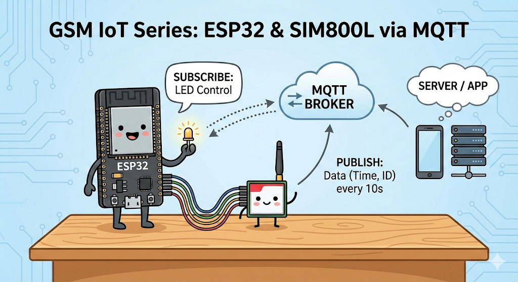
Welcome back to the GSM IoT Series! In today’s tutorial, we are taking a significant leap forward. We aren't just sending simple SMS messages anymore; we are connecting our ESP32 to the internet using the SIM800L GSM module to communicate via MQTT.
In this project, we will build a system that:
- Publishes device data (timestamp and ID) to an MQTT broker every 10 seconds.
- Subscribes to a topic to receive commands from a server (controlling an LED).
❓ Why Is This Useful?
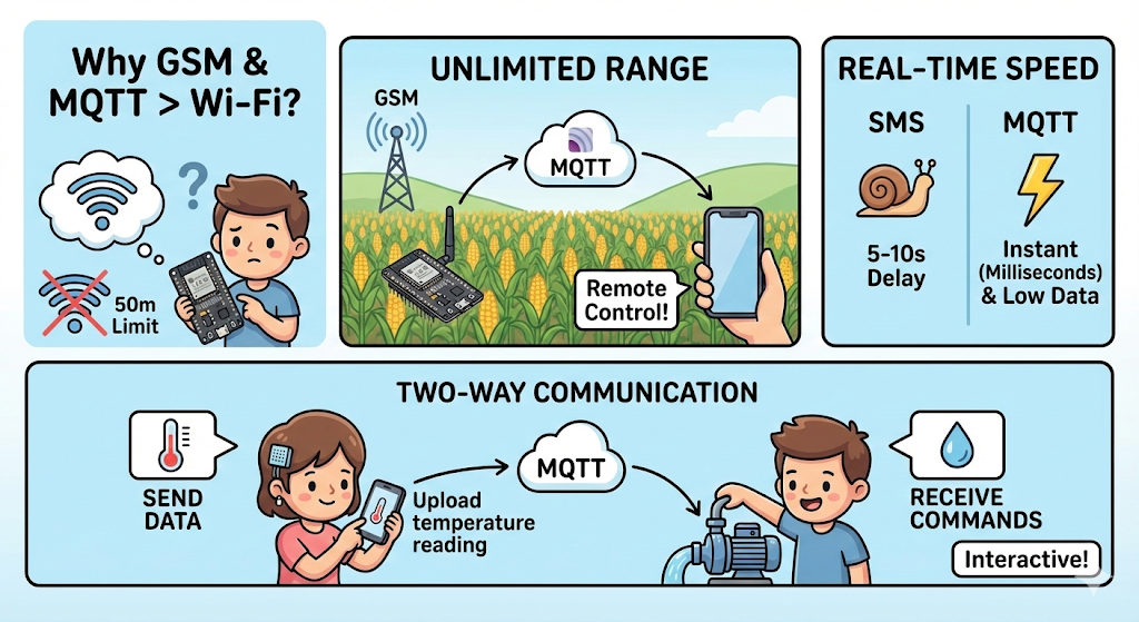
You might be thinking, "I already have Wi-Fi on my ESP32, why do I need GSM and MQTT?"
The combination of GSM (Cellular) and MQTT (Lightweight Messaging) unlocks capabilities that Wi-Fi simply cannot offer:
- Unlimited Range: Wi-Fi only reaches about 50 meters. With this setup, your device can be in the middle of a cornfield, on a moving truck, or in a remote warehouse, and you can still control it instantly from your phone.
- Real-Time Speed: Unlike SMS, which can take 5-10 seconds to arrive and costs money per message, MQTT is instant (milliseconds) and uses very little data (kilobytes). This makes it perfect for live tracking.
- Two-Way Communication: Many GSM tutorials only show you how to send data (uploading temperature). This experiment proves you can also receive commands (turn on a pump/light) instantly, making your device fully interactive.
📺 Watch the Video Tutorial
If you prefer learning visually, I have recorded a complete step-by-step walkthrough of this project. In the video, I demonstrate the hardware setup, explain the code logic in detail, and show the live bi-directional communication.
Required Component
Hardware
- SIM800L Module with the Header and Antenna soldered
- ESP32 Development Board
- Micro SIM Card (With Credit)
- Battery(Optional)
- DC-DC Booster Module (MT3608 or similar) if you use a Battery(Optional)
- 470 uF 25V Capacitor
- Breadboard
- Connecting wire
- MicroUSB Cable
Software Tools
- Arduino IDE: Make sure you have the latest version installed.
- ESP32 Board Support: You must have the ESP32 board manager installed in your IDE. Need help? Check out my guide: How to Set Up ESP32 in Arduino IDE 2.0 (Windows/Ubuntu)
- Cloud VPS: An Ubuntu-based server to host your private MQTT broker. If you want to create your personal cloud MQTT broker, then follow: Setting Up Your Private MQTT Broker on a Cloud VPS
🛑 Why a Cloud VPS? (Why not my local PC?)
A common question is: "Can I just run the MQTT broker on my laptop or a Raspberry Pi at home?"
The short answer is: No, not easily. When your SIM800L is out in the "real world" using a cellular network, it cannot "see" your home computer because:
- The Firewall Barrier: Your home router blocks incoming connections. A Cloud VPS is designed to be accessible from anywhere in the world.
- Static vs. Dynamic IP: Your home internet IP address changes frequently. A VPS provides a Static IP that never changes, so the SIM800L always knows where to send data.
- 24/7 Availability: A VPS stays online 24/7 in a data center, ensuring your IoT sensors never miss a beat.

Need help setting this up? I have written a dedicated guide on how to get your own server running: 👉 Setting Up Private MQTT Broker on Cloud VPS
Hardware Design
This is Part 5 of our GSM IoT Series. If you are new here, or if this is your first time working with these modules, I strongly recommend you pause and complete the first two tutorials. They cover the essential wiring and network stability steps you need for today's project to work:
- Part 1: How to Connect SIM800L to ESP32 (Complete Wiring Guide)
- Part 2: SIM800L Network Troubleshooting Guide (Fixing Signal & Power Issues)
🧠 The Program Flow
Before we jump into the code, let’s understand the flow of the program. I’ve designed the logic to handle network connectivity and time synchronization step-by-step:
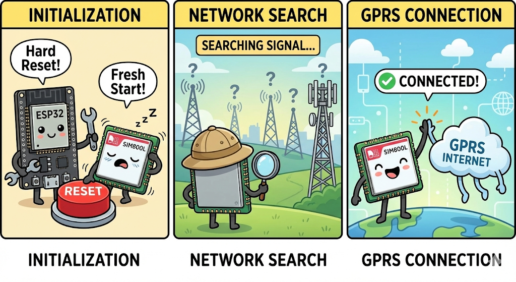
- Initialization: When the ESP32 powers on, it first performs a "Hard Reset" on the SIM800L (toggling the RST pin) to ensure the modem is fresh and ready.
- Network Search: The system scans for a cellular provider. It patiently waits until it finds a valid signal before moving forward.
- GPRS Connection: Once registered on the network, it uses your APN settings (defined in
config.h) to connect to the mobile internet.
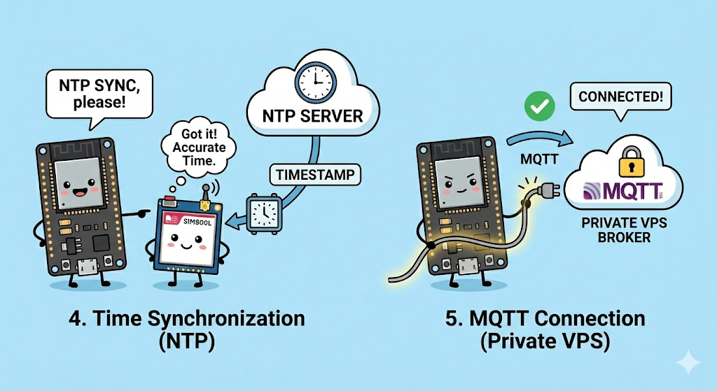
- Time Synchronization (NTP): This is a crucial step. Since the SIM800L doesn't have an internal battery to keep time, we ask the modem to sync with an NTP Server. This ensures our data points have an accurate "Timestamp" when they reach the dashboard.
- MQTT Connection: The ESP32 connects to your Private VPS Broker.
- The Loop (Heartbeat): Every 10 seconds, the device wakes up, checks if the connection is still alive, and publishes a JSON packet containing its Device ID and Current Time.
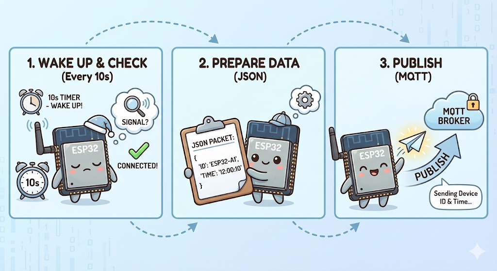
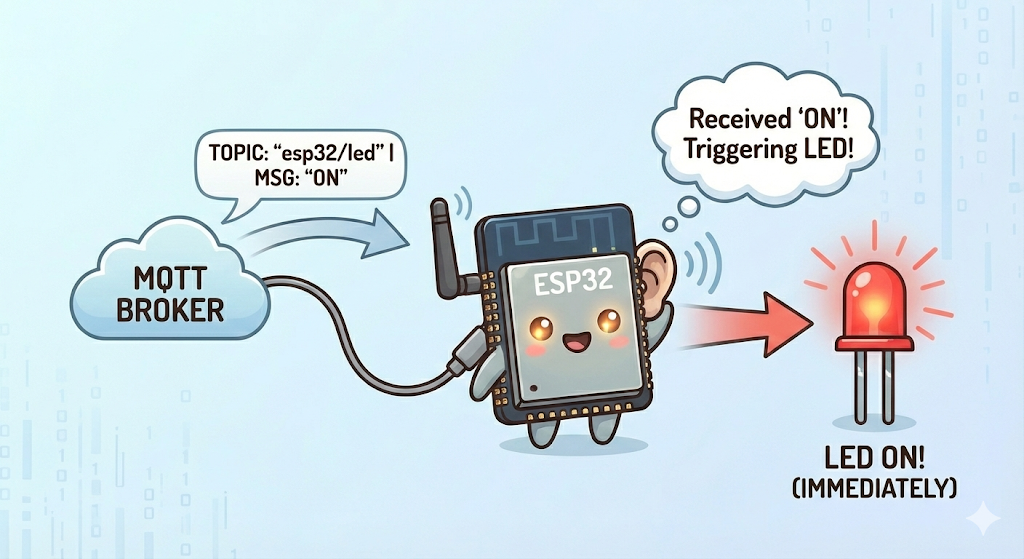
- Listening Mode: Simultaneously, the device listens for incoming messages on the
esp32/ledtopic. If it receives "ON" or "OFF", it triggers the LED immediately.
Project Structure: Setting Up in Arduino IDE
To keep our code clean and easy to edit, we will split it into two files:
config.h: Stores your settings (WiFi, APN, Pins) so you can change them easily.main.ino: Contains the actual logic and code.
Step 1: Create the Config File
- Open Arduino IDE and create a new sketch.
- Click the small arrow icon (▼) near the top right of the editor tabs.
- Select "New Tab".
- Name the file
config.hand click OK.
Step 2: Install Library
We are using 3 main libraries for this project: TinyGSM (to handle AT commands), PubSubClient (to handle MQTT) TimeLib(to handle NTP time)
Install these 3 library from arduino library manager
- TinyGSM by Volodymyr Shymanskyy (v0.12.0)
- PubSubClient >>> by Nick O'Leary (v2.8)
- TimeLib by Michael Margolis (v1.6.1)
You can copy the code below directly into your Arduino IDE, or download the complete project files from my GitHub repository.

Copy the code below and paste it into the config.h tab you just created. This is where you will edit your APN and Timezone.
Step 3: Paste the Configuration Code
Copy the code below and paste it into the config.h tab you just created. This is where you will edit your APN and Timezone.
#define SerialMon Serial
#define SerialAT Serial1
#define TINY_GSM_DEBUG SerialMon
#define GSM_PIN ""
#define NTP_SERVER "132.163.96.5"

// ESP32 and SIM800l pins
#define MODEM_TX 26
#define MODEM_RX 27
#define MODEM_RST 14
#define MODEM_DTR 25
#define MODEM_RING 34

#define BUILTIN_LED 2

// APN Settings
const char apn[] = "internet"; // put your SIM APN
const char gprsUser[] = "";
const char gprsPass[] = "";

// MQTT details
const char* mqtt_broker = "172.236.236.214"; // Your VPS IP
const int mqtt_port = 1883;
const char* mqtt_username = "user1"; // if no mqtt_username leave it blank
const char* mqtt_password = "user1"; // if no mqtt_passwrod leave it blank
const char* topic_pub = "esp32/data";
const char* topic_sub = "esp32/led";

const int UTC_OFFSET_HOURS = 6; // Define UTC offset for your timezone (e.g., +6 for Bangladesh)
const int timezoneParam = UTC_OFFSET_HOURS * 4;
const char* daysOfTheWeek[7] = {"Sunday", "Monday", "Tuesday", "Wednesday", "Thursday"
config.h
Step 4: Paste the Main Code
Now, go back to the main tab (the one with the .ino extension) and paste the following logic code. Notice how it includes #include "config.h" at the top.
This is the main program file.
#define TINY_GSM_MODEM_SIM800
#include <TinyGsmClient.h>
#include <PubSubClient.h>
#include <TimeLib.h>
#include "config.h"

#ifdef DUMP_AT_COMMANDS
#include <StreamDebugger.h>
StreamDebugger debugger(SerialAT, SerialMon);
TinyGsm modem(debugger);
#else
TinyGsm modem(SerialAT);
#endif

TinyGsmClient client(modem);
PubSubClient mqtt(client);

uint32_t lastReconnectAttempt = 0;
long lastMsg = 0;
String mqtt_client_id = "";

void mqttCallback(char* topic, byte* message, unsigned int len) {
  Serial.print("Message arrived on topic: ");
  Serial.print(topic);
  Serial.println(". Message: ");
  String incomming_message;

  for (int i = 0; i < len; i++) {
    incomming_message += (char)message[i];
  }
  incomming_message.trim();
  Serial.println(incomming_message);
  if (incomming_message == "ON") {
    Serial.println("Turning On Built-in LED");
    digitalWrite(BUILTIN_LED, HIGH);
  }
  if (incomming_message == "OFF") {
    Serial.println("Turning Off Built-in LED");
    digitalWrite(BUILTIN_LED, LOW);
  }
  Serial.println();
}

boolean mqttConnect() {
  SerialMon.print("Connecting to ");
  SerialMon.print(mqtt_broker);

  boolean status = mqtt.connect(mqtt_client_id.c_str(), mqtt_username, mqtt_password);

  if (status == false) {
    SerialMon.println(" fail");
    ESP.restart();
    return false;
  }
  SerialMon.println(" success");
  mqtt.subscribe(topic_sub);
  return mqtt.connected();
}

void setup() {
  SerialMon.begin(115200);
  delay(1000);
  pinMode(BUILTIN_LED, OUTPUT);
  digitalWrite(BUILTIN_LED, LOW);

  pinMode(MODEM_RST, OUTPUT);
  digitalWrite(MODEM_RST, LOW);
  delay(100);
  digitalWrite(MODEM_RST, HIGH);
  delay(1000);
  pinMode(MODEM_DTR, OUTPUT);
  digitalWrite(MODEM_DTR, HIGH);
  pinMode(MODEM_RING, INPUT);

  SerialMon.println("Wait ...");
  SerialAT.begin(115200, SERIAL_8N1, MODEM_TX, MODEM_RX);
  delay(3000);
  SerialMon.println("Initializing modem ...");
  modem.restart();
  delay(3000);
  modem.init();
  if (GSM_PIN && modem.getSimStatus() != 3) {
    modem.simUnlock(GSM_PIN);
  }

  SerialMon.print("Waiting for network...");
  if (!modem.waitForNetwork()) {
    SerialMon.println(" fail");
    delay(10000);
    return;
  }
  SerialMon.println(" success");

  if (modem.isNetworkConnected()) {
    SerialMon.println("Network connected");
  }

  String imei = modem.getIMEI();
  mqtt_client_id = "device-" + imei;

  SerialMon.print("Connecting to APN: ");
  SerialMon.print(apn);
  if (!modem.gprsConnect(apn, gprsUser, gprsPass)) {
    SerialMon.println(" fail");
    ESP.restart();
  }
  SerialMon.println(" OK");

  SerialMon.println("Asking modem to sync with NTP");
  modem.NTPServerSync("132.163.96.5", timezoneParam);

  // MQTT Broker setup
  mqtt.setServer(mqtt_broker, mqtt_port);
  mqtt.setCallback(mqttCallback);
}

void loop() {
  if (!mqtt.connected()) {
    SerialMon.println("=== MQTT NOT CONNECTED ===");
    uint32_t t = millis();
    if (t - lastReconnectAttempt > 10000L) {
      lastReconnectAttempt = t;
      if (mqttConnect()) {
        lastReconnectAttempt = 0;
      }
    }
    delay(100);
    return;
  }

  long now = millis();
  if (now - lastMsg > 10000) {
    lastMsg = now;
    publishDeviceData();
  }
  mqtt.loop();
}

void publishDeviceData() {
  SerialMon.println("Preparing to publish data...");
  time_t timestamp = get_timestamp();
  if (timestamp == 0) {
      SerialMon.println("Failed to get valid time. Skipping publish.");
      return;
  }
  char json_buffer[128];
  snprintf(json_buffer, sizeof(json_buffer),
           "{\"deviceId\":\"%s\",\"timestamp\":%ld}",
           mqtt_client_id.c_str(),
           timestamp);
  SerialMon.print("Publishing message: ");
  SerialMon.println(json_buffer);
  mqtt.publish(topic_pub, json_buffer);
}

int get_timestamp() {
  int year3 = 0;
  int month3 = 0;
  int day3 = 0;
  int hour3 = 0;
  int min3 = 0;
  int sec3 = 0;
  float timezone = 0;
  for (int8_t i = 5; i; i--) {
    if (modem.getNetworkTime(&year3, &month3, &day3, &hour3, &min3, &sec3, &timezone)) {
      break;
    } else {
      delay(15000L);
    }
  }
  setTime(hour3, min3, sec3, day3, month3, year3);
  return now();
}
main.ino
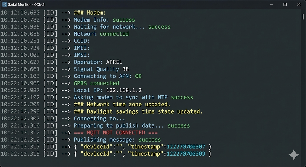
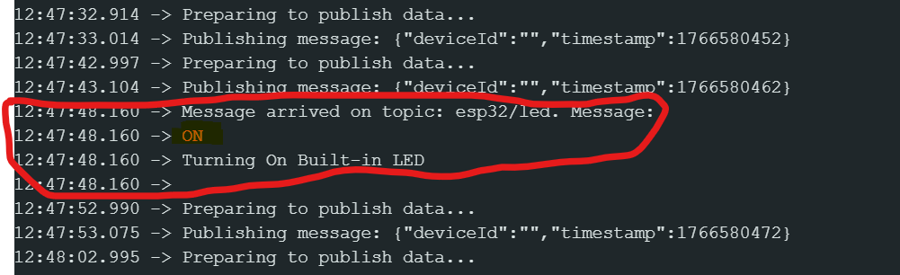
📸 Expected Serial Output
When your code uploads successfully, open your Serial Monitor (baud rate 115200). You should see the modem initializing, syncing time (NTP), and finally publishing the JSON data successfully like this:
Monitoring & Controlling with MQTTX
To interact with our ESP32, we need an MQTT Client. This acts like a dashboard where we can see incoming data and send outgoing commands. We will use MQTTX, a free and open-source tool.
🆕 New to MQTTX? If you haven't installed MQTTX yet, or if you need a step-by-step guide with screenshots on how to set it up from scratch, please read my previous tutorial first: 👉ESP32 & MQTT Beginner's Guide: Setup & Installation
Once you have MQTTX ready, use the details below to connect to this specific project:
1. Connection Setup Open MQTTX and click the "+" button to create a new connection. Fill in these details exactly as they are in your code (config.h):
- Name:
My IoT Project(or anything you like) - Host:
172.236.236.214(This is your VPS IP/broker address) - Port:
1883 - Username:
user1(If no username, then it blank) - Password:
user1(If no password, then keep it blank)
Click Connect in the top right corner. If successful, you will see a green "Connected" badge.
2. Receiving Data (Subscriber Mode) Now, let's see the data coming from the ESP32. We need to "Subscribe" to the topic the ESP32 is talking on.
- Click "+ New Subscription".
- Topic:
esp32/data - Confirm.
Wait for 10 seconds. You should start seeing JSON messages popping up like this:
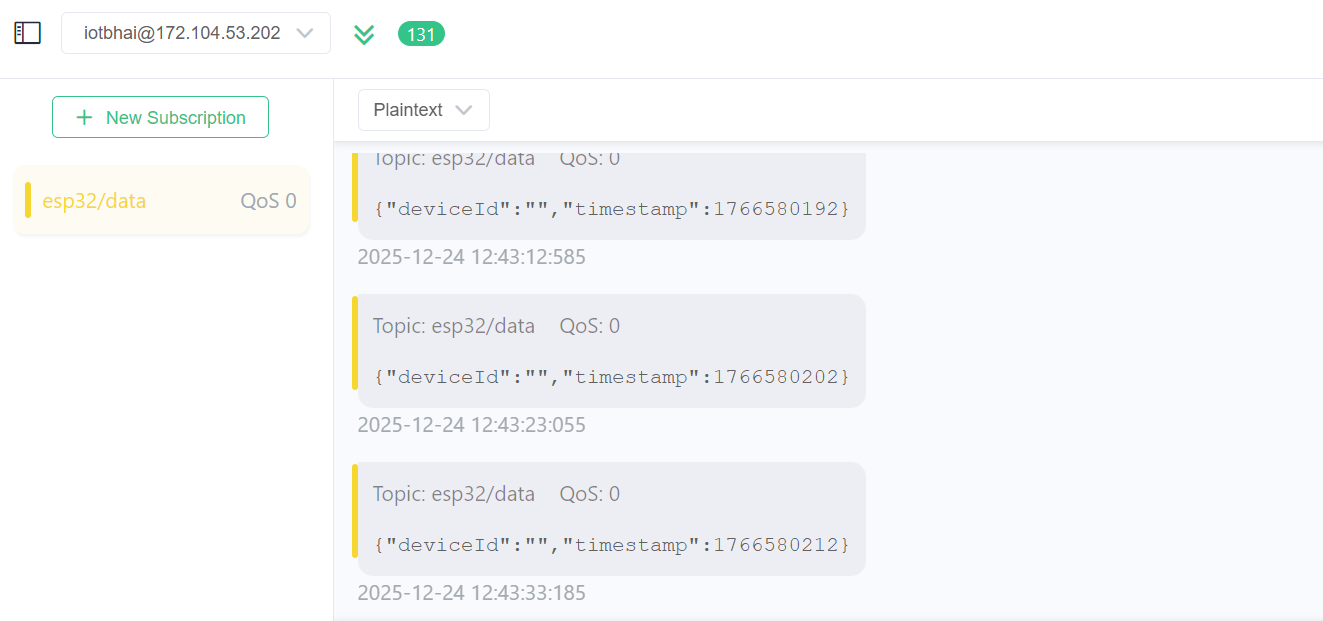
If you see this, your telemetry is working!
3. Sending Commands (Publisher Mode) Now, let's control the LED on the ESP32. We need to "Publish" a message to the topic the ESP32 is listening to.
- In the bottom message bar, find the Topic field.
- Topic:
esp32/led - Message (Payload):
ON(Make sure to use all caps, as our code checks for "ON", not "on"). - Click the Send (Paper Plane) icon.
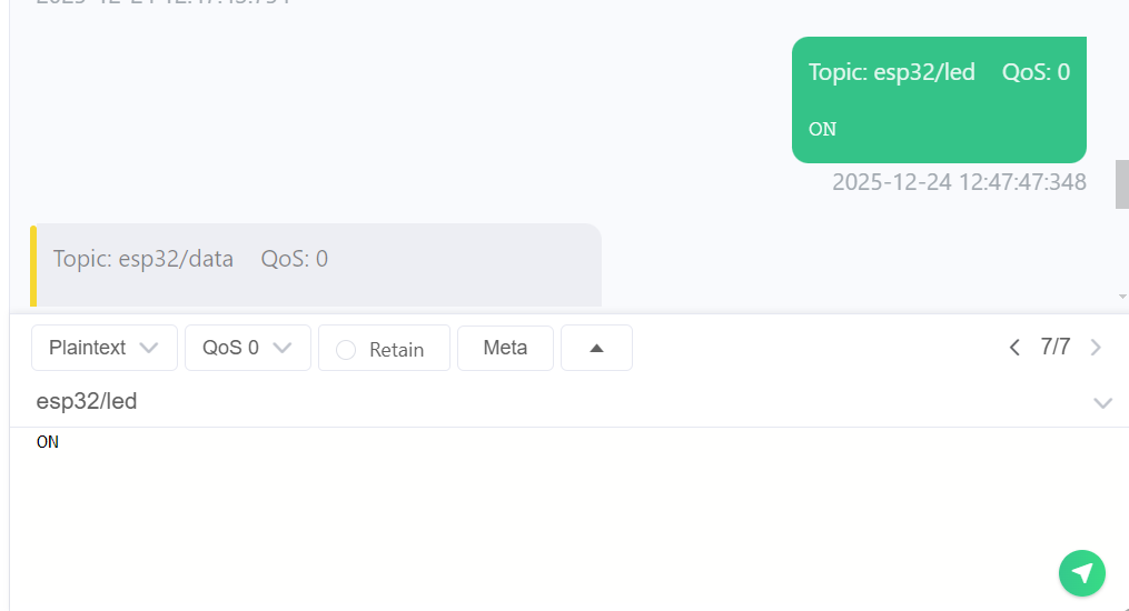
Result: Look at your hardware setup. The Blue LED should turn ON instantly! Send OFF to turn it back down.
The Code Logic
Key Functions:
setup(): We initialize the modem and connect to the GPRS network using your SIM card's APN. We also sync the time usingmodem.NTPServerSyncso our data has correct timestamps.mqttCallback(): This is the "listening" function. When the broker sends a command:- If the payload is "ON" ➡ Turn Built-in LED HIGH.
- If the payload is "OFF" ➡ Turn Built-in LED LOW.
publishDeviceData():- This function creates a JSON string containing the Device ID (based on IMEI) and the Timestamp.
- It publishes this data to the topic
esp32/dataevery 10 seconds.
⚠️ Important Note: The 2G Sunset
While the SIM800L is a fantastic, low-cost module for learning, please remember that it is a 2G-only device.
Many countries and cellular providers are shutting down their 2G towers to transition to 4G and 5G.
- For Learning: SIM800L is perfect.
- For Professional Products: I strongly recommend looking into 4G LTE modules like the SIM7600 or the A7670G. I have a separate playlist dedicated to the A7670 series on my channel if you want to future-proof your projects.
Conclusion
Connecting your ESP32 to MQTT via GSM opens up a world of possibilities where Wi-Fi isn't available—like tracking vehicles, monitoring remote farms, or smart city projects.
If you found this tutorial helpful, don't forget to check out the video version on IoT Bhai. In the next tutorial, we will explore more advanced examples!