SIM800L Network Connection Guide: The Ultimate Troubleshooting Checklist(GSM IoT Series #2)
Stuck with the dreaded 'fast blink' on your GSM module? 90% of SIM800L issues come down to power. Discover the capacitor hack and the exact voltage settings you need to get your IoT project online, whether you use an ESP32 or Arduino.
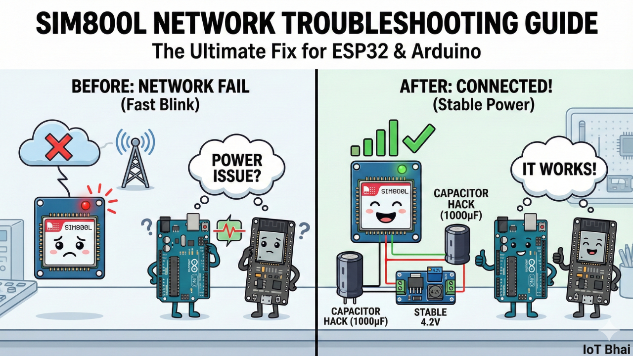
Can’t get a signal? Stuck with the "fast blink" error? Here is how to fix SIM800L power and network issues for good, regardless of which microcontroller you use.
Watch the Full Troubleshooting Guide
Prefer to see the solution in action? Watch the step-by-step tutorial below where we demonstrate the "failure mode" vs. the "success mode" live.
Watch Full SIM800L Troubleshooting guide on Youtube
Introduction
The SIM800L is one of the most popular GSM modules for IoT projects because of its small size and low cost. But whether you are connecting it to an Arduino Uno, ESP32, STM32, or Raspberry Pi, the #1 problem everyone faces is the same:
The module refuses to connect to the cellular network.
You’ve likely seen the symptom: the onboard LED blinks furiously (every second) and never slows down. In this guide, based on the troubleshooting deep-dive by IoT Bhai, we will fix the root causes of this issue so you can get your project online.
Required Component
Hardware
- SIM800L Module with the Header and Antenna soldered
- ESP32 Development Board
- Micro SIM Card (With Credit)
- Battery(Optional)
- DC-DC Booster Module (MT3608 or similar) if you use a Battery(Optional)
- 470 uF 25V Capacitor
- Breadboard
- Connecting wire
- MicroUSB Cable
Software Tools
- Arduino IDE: Make sure you have the latest version installed.
- ESP32 Board Support: You must have the ESP32 board manager installed in your IDE. Need help? Check out my guide: How to Set Up ESP32 in Arduino IDE 2.0 (Windows/Ubuntu)
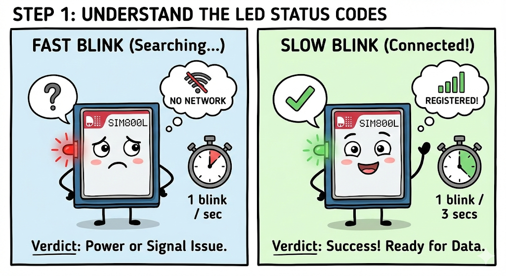
Step 1: Understand the LED Status Codes
Before you blame your code or your microcontroller, look at the LED on the SIM800L. It tells you exactly what is happening.
- Fast Blink (1 blink every second):
- Status: Searching for network / Not connected.
- Verdict: If it stays like this for more than 10-15 seconds, you have a power or signal issue.
- Slow Blink (1 blink every 3 seconds):
- Status: Registered to network.
- Verdict: Success! Your hardware is working, and the module is ready to send/receive data.
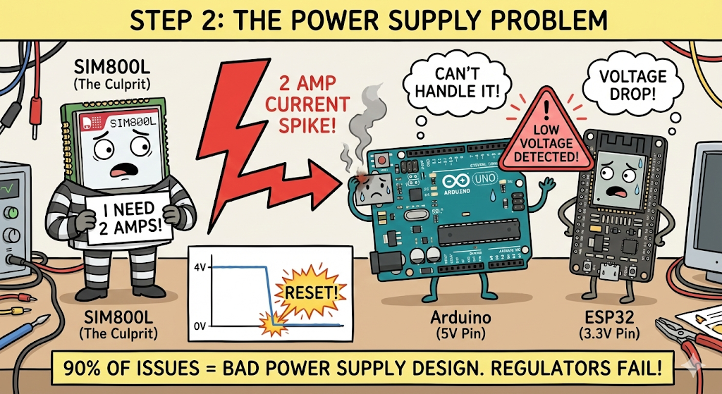
Step 2: The Power Supply (The #1 Culprit)
90% of SIM800L issues are caused by bad power supply design.
The Physics of the Problem: The SIM800L runs on a voltage range of 3.4V to 4.4V. However, when it tries to talk to a cell tower, it pulls a massive 2 Amp current spike for a fraction of a second.
- If you power it directly from an Arduino's 5V pin: It will fail.
- If you power it directly from an ESP32's 3.3V pin: It will fail (and might reset your board).
Most microcontroller regulators cannot handle that 2A spike fast enough. The voltage drops, the SIM800L detects "low voltage," and it shuts down or resets immediately.
Since you cannot rely on your microcontroller's power pins, you must use a dedicated external power source capable of handling the load.
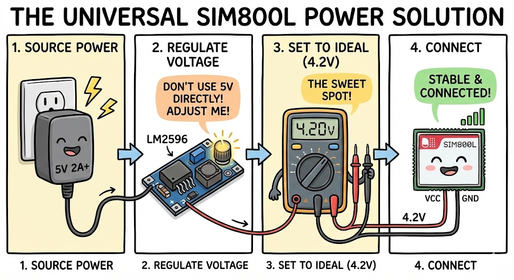
The most reliable, universal method for powering the SIM800L is:
- Source Power: Use a high-quality 5V DC Adapter (like a wall wart or a good phone charger) that is rated for at least 2 Amps (or higher).
- Regulate Voltage: Do NOT connect 5V directly to the SIM800L (it is outside the safe operating range for many modules). Connect your 5V adapter to an adjustable DC-DC Step-Down (Buck) Converter module (such as an LM2596).
- Set to Ideal: Use a multimeter and adjust the step-down module's output to exactly 4.2V. This is the "sweet spot" for SIM800L stability.
- Connect: Connect this stable 4.2V output to the SIM800L's VCC pin.
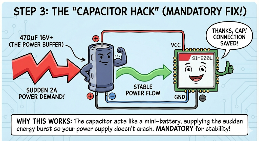
Step 3: The "Capacitor Hack" (Mandatory Fix)
The most effective fix for network stability is adding a power buffer.
What to do: Solder or connect an Electrolytic Capacitor directly across the VCC and GND pins of the SIM800L module.
- Recommended Value: 470uFµF (16V or higher).
- Connection:
- Positive leg (+) to SIM800L VCC.
- Negative leg (-) to SIM800L GND.
Why this works: When the module demands that sudden 2A burst, it pulls energy from the capacitor instead of crashing your power supply.
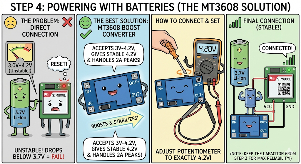
Step 4: Voltage Selection & Batteries (The Battery Solution)
Since the SIM800L is extremely sensitive to voltage (its absolute high limit is 4.4V), you have to be very careful when choosing a power source.
The Problem with Direct Battery Connection: Many beginners try to connect a standard 3.7V Li-Ion or Li-Po battery directly to the SIM800L. While this can work temporarily when the battery is fully charged (around 4.2V), it quickly becomes unstable. As the battery drains and its voltage drops below 3.7V, the SIM800L will fail to connect or will constantly reset under load.
The Best Solution: Use an MT3608 Boost Converter
Instead of connecting the battery directly, the most reliable method is to use a dedicated boost converter module to ensure a stable voltage regardless of the battery's charge level.
We highly recommend using the MT3608 DC-DC Boost Converter Module.
Why the MT3608 is perfect for this:
- Wide Input Range: It easily accepts the varying voltage from a single-cell Li-Ion battery (3V - 4.2V).
- Adjustable Output: It has a small potentiometer (screw) that allows you to precisely boost and tune the output voltage. You should set it to exactly 4.2V, which is the ideal operating voltage for the SIM800L.
- High Current Capability: The MT3608 is capable of handling the 2A current peaks that the SIM800L requires during network transmission, ensuring your module doesn't crash.
How to connect it:
- Connect your Li-Ion battery terminals to the IN+ and IN- pads of the MT3608 module.
- Before connecting the SIM800L, use a multimeter to measure the voltage at the OUT+ and OUT- pads.
- Turn the small screw on the blue potentiometer until your multimeter reads exactly 4.2V.
- Once set, connect the OUT+ to the SIM800L's VCC and OUT- to the GND.
(Note: Even with this stable booster, keep the capacitor from Step 3 installed for maximum reliability!)
Step 5: SIM Card & Antenna
If your power is perfect but you still have the "Fast Blink," check the physical connection:
- SIM Orientation: On most SIM800L slots, the notched corner of the Micro-SIM usually faces outward. Ensure it clicks into place.
- Antenna: The coil antenna (spring) must be soldered to the
NETpin. If you are in an area with poor signal, the small coil antenna might not be enough. Consider snapping an external GSM antenna onto the IPEX connector if your board has one. - SIM Status: Ensure the SIM card has an active plan and is not PIN-locked.
A "Last Resort" Tip: Try 5V
If you have tried absolutely everything above—the capacitor, the regulated 4.2V source, different SIM cards—and it still won't connect, here is one final thing to try.
While the official datasheet states a maximum of 4.4V, many common SIM800L breakout boards (especially the red ones) include an onboard diode on the VCC pin. This diode drops the voltage by about 0.7V.
Because of this diode drop, many users find that their specific modules actually work best when supplied with a stable 5V source (still requiring 2A capability).
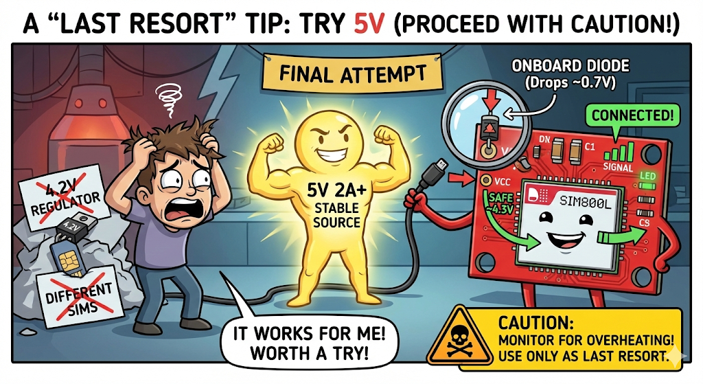
If nothing else works, try powering the VCC pin with a stable 5V (from your 2A adapter) to see if the network connects. I use 5V on many of my own devices successfully. Proceed with caution and monitor the module for overheating.
Hands-On Connection Guides (ESP32 & Arduino)
Once you have your power supply sorted, wiring the data pins depends on your microcontroller. Watch these specific tutorials to see how to wire the RX/TX pins and set up the code for your board.
1. For ESP32 Users
In this video, we show you how to wire the SIM800L to an ESP32, handling the 3.3V logic levels correctly, and running a network test.
2. For Arduino Uno Users
Connecting to an Arduino Uno requires careful wiring because of the 5V logic. In this video, we demonstrate the voltage divider method for the RX pin to prevent damaging your SIM module.Watch: How to Connect SIM800L to Arduino Correctly | GSM Bootcamp Part 1