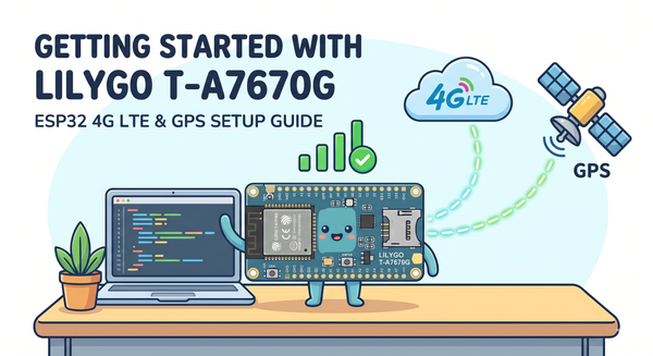
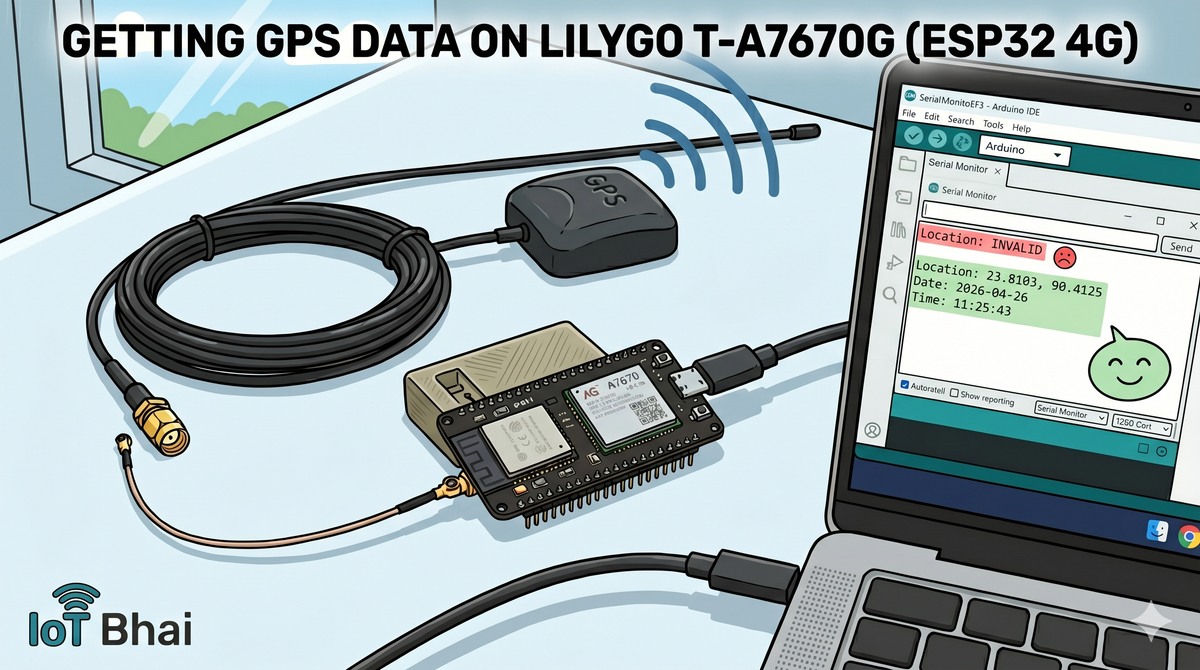
How to Get GPS Data with LILYGO T-A7670G (ESP32 4G LTE)
Learn how to extract precise GPS location data using the LILYGO T-A7670G. This step-by-step tutorial covers hardware setup, active antenna connections, and the Arduino code needed for your ESP32 IoT projects.
In our previous guide, we covered the basics of getting started with the LILYGO T-A7670G. If you haven't seen that yet, be sure to check out the LILYGO T-A7670G 4G ESP32 Setup Guide first.
Today, we are taking it a step further by testing the integrated GPS module. The LILYGO T-A7670G is a fantastic board for remote IoT projects because it combines an ESP32, a 4G LTE module (A7670), and a dedicated GPS module all in one package.
In this tutorial, I’ll show you how to connect the GPS antenna, write a simple Arduino sketch to extract the location data, and view it directly in the Serial Monitor.
Prerequisites: Hardware Checklist
To follow along with this setup, you will need:
- LILYGO T-A7670G Development Board
- Active GPS Antenna with SMA Male Plug (need for connecting with board)
- Active GPS Antenna only
- 🛒 Buy on AliExpress ("SMA Male-L")
- IPX to SMA Connector Cable SMA
- 🛒 Buy on AliExpress ("IPX to SMA-KY")
- Active GPS Antenna only
- USB Type-C Cable
A Quick Note on GPS Antennas
The board usually comes with a small, passive GPS antenna. If you are working outdoors, this works perfectly fine. However, because I am recording and testing inside my room, getting a satellite lock is difficult.
For indoor testing (or if your final project will be enclosed), I highly recommend using an Active GPS Antenna with a long wire. This allows you to place the antenna outside a window while keeping the board on your desk.
Watch the Video Tutorial
If you prefer learning visually, I have put together a complete step-by-step video walkthrough of this project.
⚙️ Hardware Setup
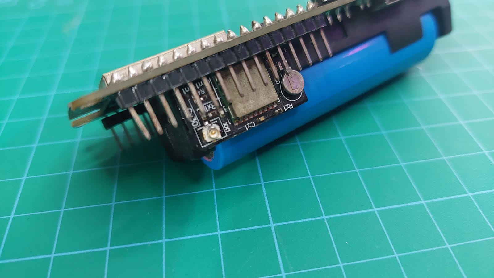
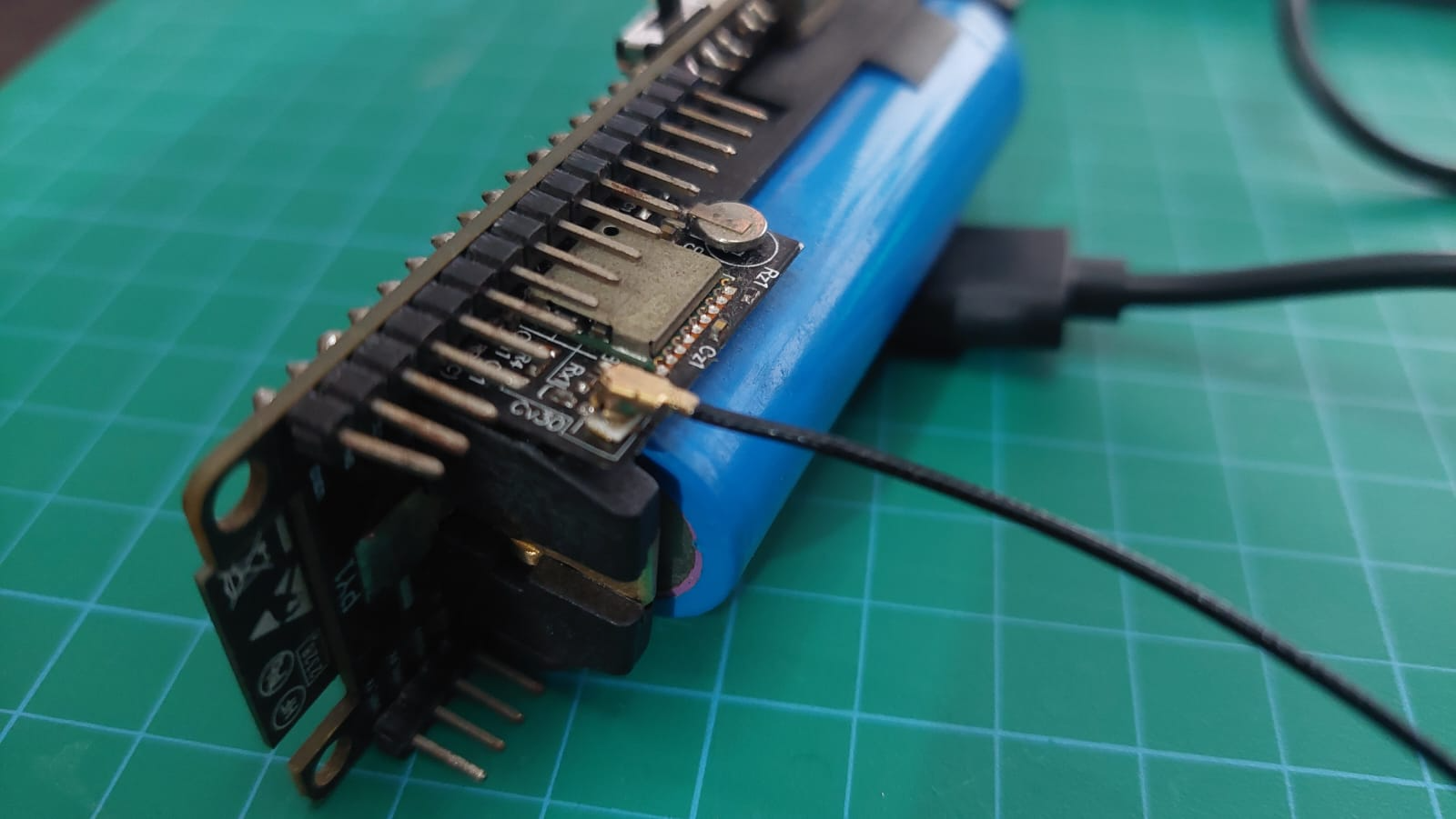
- Attach the Converter: Carefully snap the small IPEX (U.FL) end of the converter cable onto the designated GPS port on the LILYGO board. Be gentle, as these tiny connectors are fragile!
- Connect the Antenna: Screw your active GPS antenna's SMA connector into the other end of the converter cable.
- Position the Antenna: If you are indoors, route the receiver node outside a window to ensure a clear view of the sky.
- Power Up: Connect the board to your computer using a data-capable USB-C cable.
💻 The Code
We will be using the hardware serial of the ESP32 to communicate with the internal GPS module. The code is very straightforward—it initializes the connection and continuously checks for incoming location, date, and time data.
#define SerialAT Serial1
#define SerialGPS Serial2

#define BOARD_MODEM_DTR_PIN                 25
#define BOARD_MODEM_TX_PIN                  26
#define BOARD_MODEM_RX_PIN                  27
#define BOARD_MODEM_PWR_PIN                 4
#define BOARD_ADC_PIN                       35
#define BOARD_POWER_ON_PIN                  12
#define BOARD_MODEM_RI_PIN                  33
#define BOARD_RST_PIN                       5

#define BOARD_GPS_TX_PIN                    21
#define BOARD_GPS_RX_PIN                    22
#define BOARD_GPS_PPS_PIN                   23
#define BOARD_GPS_WAKEUP_PIN                19


#include <Arduino.h>
#include <TinyGPS++.h>

TinyGPSPlus gps;


void setup()
{
    pinMode(BOARD_POWER_ON_PIN, OUTPUT);
    digitalWrite(BOARD_POWER_ON_PIN, HIGH);
    pinMode(BOARD_RST_PIN, OUTPUT);
    digitalWrite(BOARD_RST_PIN, LOW);
    pinMode(BOARD_MODEM_PWR_PIN, OUTPUT);
    digitalWrite(BOARD_MODEM_PWR_PIN, LOW);
    delay(100);
    digitalWrite(BOARD_MODEM_PWR_PIN, HIGH);
    delay(1000);
    digitalWrite(BOARD_MODEM_PWR_PIN, LOW);
    Serial.begin(115200);
    SerialAT.begin(115200, SERIAL_8N1, BOARD_MODEM_RX_PIN, BOARD_MODEM_TX_PIN);
    SerialGPS.begin(9600, SERIAL_8N1, BOARD_GPS_RX_PIN, BOARD_GPS_TX_PIN);
    delay(2000);

}

void loop()
{
    while (SerialGPS.available()) {
        int c = SerialGPS.read();
        if (gps.encode(c)) {
            displayInfo();
        }
    }
    if (SerialAT.available()) {
        Serial.write(SerialAT.read());
    }
    if (Serial.available()) {
        SerialAT.write(Serial.read());
    }
    delay(1000);
}


void displayInfo()
{
    Serial.print(F("Location: "));
    if (gps.location.isValid()) {
        Serial.print(gps.location.lat(), 6);
        Serial.print(F(","));
        Serial.print(gps.location.lng(), 6);
    } else {
        Serial.print(F("INVALID"));
    }

    Serial.print(F("  Date/Time: "));
    if (gps.date.isValid()) {
        Serial.print(gps.date.month());
        Serial.print(F("/"));
        Serial.print(gps.date.day());
        Serial.print(F("/"));
        Serial.print(gps.date.year());
    } else {
        Serial.print(F("INVALID"));
    }

    Serial.print(F(" "));
    if (gps.time.isValid()) {
        if (gps.time.hour() < 10) Serial.print(F("0"));
        Serial.print(gps.time.hour());
        Serial.print(F(":"));
        if (gps.time.minute() < 10) Serial.print(F("0"));
        Serial.print(gps.time.minute());
        Serial.print(F(":"));
        if (gps.time.second() < 10) Serial.print(F("0"));
        Serial.print(gps.time.second());
        Serial.print(F("."));
        if (gps.time.centisecond() < 10) Serial.print(F("0"));
        Serial.print(gps.time.centisecond());
    } else {
        Serial.print(F("INVALID"));
    }

    Serial.println();
}
Uploading the Code
- Open the Arduino IDE.
- Select your ESP32 board and the correct COM port.
- Hit Upload.
📊 Testing and Results
Once the code is uploaded, open your Serial Monitor and set the baud rate (115200).
11:25:37.045 -> Initializing GPS Module...
11:25:38.102 -> Location: INVALID  Date: INVALID  Time: INVALID
11:25:39.104 -> Location: INVALID  Date: INVALID  Time: INVALID
11:25:40.106 -> Location: INVALID  Date: INVALID  Time: INVALID
11:25:41.150 -> Location: INVALID  Date: 2026-04-26 Time: 11:25:41
11:25:42.152 -> Location: INVALID  Date: 2026-04-26 Time: 11:25:42
11:25:43.400 -> Location: 23.8103, 90.4125  Date: 2026-04-26 Time: 11:25:43
11:25:44.402 -> Location: 23.8103, 90.4125  Date: 2026-04-26 Time: 11:25:44
11:25:45.405 -> Location: 23.8104, 90.4125  Date: 2026-04-26 Time: 11:25:45
🏁 Conclusion & What's Next?
Extracting the raw GPS data is just the first step in unlocking the full potential of the LILYGO T-A7670G. We’ve successfully established a satellite lock and read the coordinates using the ESP32, proving how capable this all-in-one board is for location tracking.
Now that we have the GPS working perfectly, it’s time to test its cellular capabilities!
In our next tutorial, we will dive into SMS testing. I will walk you through how to send and receive text messages using the onboard A7670 4G LTE module. This is a crucial feature for building remote IoT systems, as it allows your device to send location alerts or receive remote commands from anywhere in the world.
Make sure to subscribe to the YouTube Channel and bookmark the blog so you don't miss the SMS tutorial when it drops!