How to Connect ESP32 to AWS IoT Core Without Wi-Fi Using SIMA7670G (Full Tutorial)
Learn how to connect your ESP32 to AWS IoT Core over 4G LTE using the SIMA7670G module — no Wi-Fi needed. Step-by-step guide covering AWS setup, TLS certificates, and two-way MQTT communication.
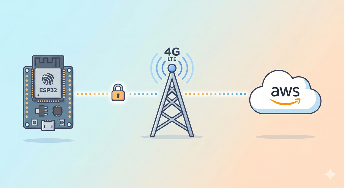
Most ESP32 AWS IoT tutorials assume you have a stable Wi-Fi connection. But what happens when you need to deploy a sensor in a remote field, a vehicle, or an outdoor enclosure where Wi-Fi simply doesn't reach? That's exactly the problem this tutorial solves.
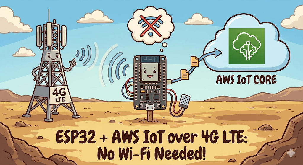
In this guide, you'll learn how to connect your ESP32 to AWS IoT Core over 4G LTE using the SIMA7670G cellular module — no Wi-Fi required. By the end, your ESP32 will be publishing sensor data to the cloud and receiving commands back, all over a secure MQTT connection via cellular.
Table of Contents
- Why Use Cellular Instead of Wi-Fi?
- Hardware You Will Need
- Circuit Wiring Diagram
- Setting Up AWS IoT Core
- Generating and Organizing Your Certificates
- The Arduino Code — Deep Dive
- Testing with the AWS MQTT Test Client
- Troubleshooting Common Issues
- What to Build Next
Watch the Video Tutorial
If you prefer learning visually, I have put together a complete step-by-step video walkthrough of this project.
1. Why Use Cellular Instead of Wi-Fi?
Wi-Fi is convenient in a lab, but it has serious limitations for real-world IoT deployments:
- Range: Wi-Fi covers roughly 30–50 meters indoors. Cellular covers kilometers.
- Reliability: Wi-Fi routers go offline, passwords change, and networks get congested. A SIM card on a cellular network is far more dependable for 24/7 uptime.
- Portability: Vehicles, agriculture sensors, and remote monitoring systems cannot rely on fixed infrastructure.
The SIMA7670G is a modern 4G LTE Cat-1 module — a major upgrade over the older SIM800L (which used 2G). It supports faster data rates, TLS 1.2 (required by AWS), and has better global carrier compatibility.
2. Hardware You Will Need
Before we begin, ensure you have the following components ready:
- ESP32 Development Board (e.g., DOIT DevKit V1 or similar).
- SIM A7670G Breakout Board (Ensure it comes with the LTE and GPS antennas).
- A Nano SIM Card with an active 4G data plan.
- Jumper Wires (Female-to-Male or Female-to-Female depending on your board headers).
- CRITICAL: A Stable External Power Supply (Rated 5V, capable of delivering at least 2.5A current).
- Micro USB Cable (optional), if you want to power the sim module via usb port
The Hardware Setup
The wiring remains the same as Part 1. If you have not wired your module yet, or if you are unsure about the power requirements, please refer to our detailed setup guide here:
👉Read Part 1: Connect SIM A7670G with ESP32 - Hardware & Wiring Guide
⚠️ Important: Ensure your SIM module is powered by an external 5V 2A power source, not the ESP32.
Software Setup:
- Arduino IDE: Make sure you have the latest version installed.
- ESP32 Board Support: You must have the ESP32 board manager installed in your IDE. Need help? Check out my guide: How to Set Up ESP32 in Arduino IDE 2.0 (Windows/Ubuntu)
3. Why AWS IoT Core?
AWS IoT Core is Amazon's managed MQTT broker built specifically for IoT devices. Here's why it's a great choice:
- Secure by default: Every connection is TLS 1.2 encrypted with mutual certificate authentication — no username/password that can be guessed
- Scales from 1 to millions: The same setup works whether you have 1 device or 10,000
- Free tier: Up to 500,000 messages/month free — more than enough for hobby and small commercial projects
- Ecosystem: Messages flow directly into DynamoDB, Lambda, S3, SNS and dozens of other AWS services with zero extra code
3. Setting Up AWS IoT Core — Step by Step
Step 1: Create a Thing
- Log in to the AWS Management Console
- Navigate to IoT Core → Manage → Things
- Click Create things → Create a single thing
- Name it something descriptive like
ESP32_Cellular_Sensor - Leave the device shadow as default → click Next
Step 2: Generate and Download Certificates
On the certificate page, choose Auto-generate a new certificate.
Step 3: Create and Attach a Policy
Navigate to Security → Policies → Create policy
First, give your policy a clear name — something like ESP32_Cellular_AWS_Policy. Avoid spaces; use underscores or hyphens. You'll need to find this name again in the next step, so make it recognizable and use this JSON:
{
  "Version": "2012-10-17",
  "Statement": [
    {
      "Effect": "Allow",
      "Action": [
        "iot:Connect",
        "iot:Publish",
        "iot:Subscribe",
        "iot:Receive"
      ],
      "Resource": "*"
    }
  ]
}
Security Note: The "Resource": "*" wildcard is fine for development. For production, restrict this to specific topic ARNs to follow the principle of least privilege.Click Create to save the policy.
Step 3: Download the certificate
After creating the policy, you need to attaching the Policy to Your Certificate manually. Go to the certificate page and select the newly created policy. Then click on create things, and a certificate page will appear.
Download all three files immediately — you cannot download the private key again after leaving this screen:
| File | What It Is |
|---|---|
xxxxxxxxxx-certificate.pem.crt | Your device's identity certificate |
xxxxxxxxxx-private.pem.key | The private key (keep this secret!) |
AmazonRootCA1.pem | Amazon's root CA (verifies AWS is AWS) |
Also, copy your AWS IoT Endpoint from: Here are the exact steps to find your AWS IoT Endpoint in the updated console:
- In the AWS IoT Core console, look at the main navigation menu on the far left.
- Near the top, click to expand the Connect section.
- Click on Domain configurations.
- Click on your active domain name from the list.
- In the details page, look for the Domain name.
- It will look something like
xxxxxxxxxxxxxx-ats.iot.[region].amazonaws.com.
4. Organizing Your Certificates (The Clean Way)
Instead of pasting long certificate strings directly into your main .ino file, we keep each credential in its own header file. This keeps your main sketch clean and makes it easy to swap credentials for different devices.
Create three files inside your Arduino sketch folder:
certificate.h
const char* certificate = R"EOF(
-----BEGIN CERTIFICATE-----
// Paste your Device Certificate (.pem.crt) content here
-----END CERTIFICATE-----
)EOF";
private_key.h
const char* private_key = R"EOF(
-----BEGIN RSA PRIVATE KEY-----
// Paste your Private Key (.pem.key) content here
-----END RSA PRIVATE KEY-----
)EOF";
root_CA.h
const char* root_CA = R"EOF(
-----BEGIN CERTIFICATE-----
// Paste your Amazon Root CA 1 content here
-----END CERTIFICATE-----
)EOF";
5. The Arduino Code — Deep Dive
With the hardware already set up from Part 1, here is the complete sketch for AWS IoT Core over cellular.
Software Setup (The TinyGSM Library)
To communicate with the modem using AT commands without writing complex parsing code, we rely on the TinyGSM library.
⚠️ Crucial Library Warning
The standard version of TinyGSM found in the Arduino Library Manager may not fully support the A7670G's specific AT command set yet.
For this tutorial to work, you must use the specific fork linked below:
- Download Library: https://github.com/lewisxhe/TinyGSM-fork
Installation Instructions:
- Download the repository as a
.zipfile from GitHub. - Open Arduino IDE.
- Go to Sketch -> Include Library -> Add .ZIP Library...
- Select the downloaded file.
Full source code is available on the IoT Bhai GitHub.
6. Testing with the AWS MQTT Test Client
Conclusion
You've now built a cellular IoT device that can communicate securely with the cloud from anywhere with a 4G signal. The key things that make this tutorial work are:
- The SIMA7670G handles TLS natively — no extra SSL library on the ESP32 side needed
- Separating credentials into their own header files keeps code clean and credentials out of version control
- The AWS MQTT test client is the fastest way to confirm end-to-end connectivity before building anything on top
- Always include reconnection logic in
loop()— cellular connections can drop unexpectedly
Full source code is available on the IoT Bhai GitHub. If you run into issues, drop a comment on the YouTube video.