IntroductionIf you're working with ESP32 and MQTT, one of the first things you'll want to do is see the data your device is sending and test commands going back to it.
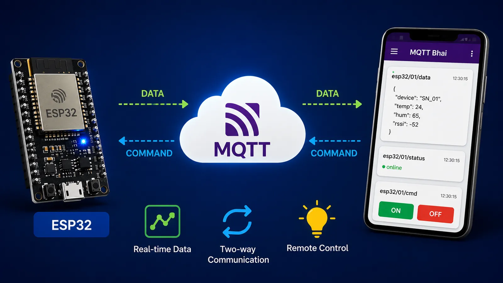
In this tutorial, we'll build a simple two-way MQTT communication system using an ESP32 and the MQTT Bhai Android app.
The ESP32 will:
- Connect to Wi-Fi
- Connect to an MQTT broker
- Publish sensor data
- Subscribe to an MQTT command topic
- Turn its onboard LED ON or OFF based on MQTT commands
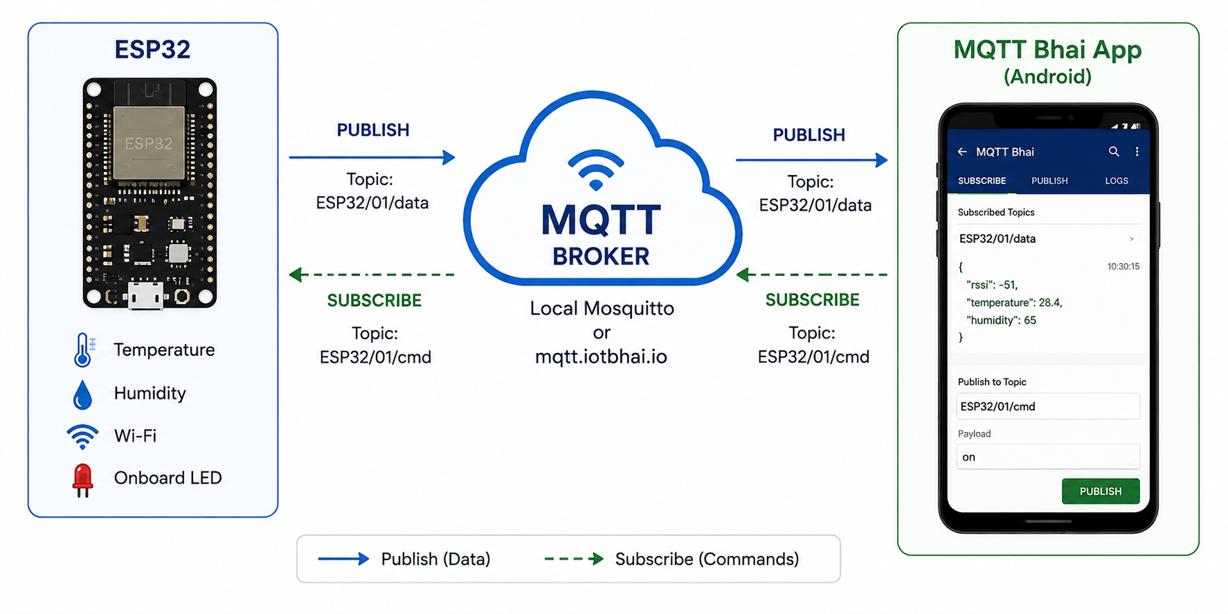
And on the other side, we'll use MQTT Bhai to monitor the incoming messages and control the ESP32 in real time. You can run everything on your local network using a Raspberry Pi + Mosquitto, or connect your ESP32 from anywhere using a public MQTT broker such as mqtt.iotbhai.io.
Here is the detailed block diagram of how the whole process works
🎥 Watch the Full Tutorial
I've also covered this project step by step in the video below.
If you're new to MQTT, I recommend watching the video first and then using this article as a reference while building your own project.
🛠️ What You'll Need
You don't need much hardware for this project.
ESP32 Development Board (e.g., DOIT DevKit V1 or similar).
Android Smartphone
- USB Cable — Micro-USB or USB Type-C depending on your ESP32 board
- Raspberry Pi — optional, if you want to run your own local MQTT broker
- MQTT broker (For the MQTT broker, you can use a local Mosquitto installation, your own private VPS broker, or the public IoTBhai broker used in this tutorial.)
We need an MQTT Client to see the incoming messages and send commands to the device, so we are using the MQTT Bhai client app. MQTT Bhai lets you connect to an MQTT broker, subscribe to topics, monitor incoming messages, and publish commands—all from one simple interface.
- Arduino IDE
The ESP32 will handle the IoT side, while the Android phone will be used to monitor messages and send commands using MQTT Bhai.
☁️ Step 1: Set Up an MQTT Broker
Before connecting the ESP32 and MQTT Bhai, you need an MQTT broker. The broker acts as the middleman between your ESP32 and MQTT Bhai.
For this tutorial, you can use either a local Raspberry Pi broker, the IoTBhai public broker, or your own private MQTT broker.
Option A: Raspberry Pi + Mosquitto
If you want to run your own MQTT broker locally, you can install Mosquitto on a Raspberry Pi.
I've already covered the complete Raspberry Pi MQTT broker setup in a separate video:
After completing the setup, you'll need the Raspberry Pi's local IP address, for example:
Broker: 192.168.0.104
Port:   1883
Your ESP32 and Android phone should be connected to the same local network.
Option B: IoTBhai Public MQTT Broker
If you want to start testing without setting up your own server, you can use the public MQTT broker:
Broker: mqtt.iotbhai.io
Port:   1883
This is the broker we'll use for the examples in this tutorial.
Option C: Your Own Private Cloud MQTT Broker
If you're building a larger or production IoT system, you can also run your own Mosquitto broker on a cloud VPS.
👉 Setting Up a Private MQTT Broker on a Cloud VPS
For this tutorial, however, we'll keep things simple and use mqtt.iotbhai.io.
Note: The public broker is intended for experimentation and learning. For production deployments, use proper authentication, access control, and TLS/SSL encryption.
📱 Step 2: Configure MQTT Bhai
Open MQTT Bhai and create a new MQTT connection.

For this tutorial, enter:
Broker: mqtt.iotbhai.io
Port:   1883
Save the connection and connect to the broker.
Once connected, MQTT Bhai is ready to monitor the ESP32 and send commands.
💻 Step 3: Program the ESP32
Now let's look at what the ESP32 actually does.
The complete Arduino sketch is available in the project resources, but let's understand the important parts first.
The project uses three MQTT topics:
esp32/01/data
esp32/01/cmd
esp32/01/status
Each topic has a specific purpose.
| Topic | Purpose |
|---|---|
esp32/01/data | ESP32 telemetry |
esp32/01/cmd | Commands sent to ESP32 |
esp32/01/status | Online/offline status |
This topic structure makes the project easier to expand later.
Step 4: Complete ESP32 MQTT Code
📂 Get the Complete Code on GitHub
You can copy the code directly from this article, but I've also uploaded the complete project to GitHub.
👉 View the ESP32 MQTT Tutorial on GitHub
Now that the MQTT broker and MQTT Bhai are ready, let's program the ESP32.
The following is the complete Arduino sketch used in this tutorial.
Required Arduino Libraries
Before compiling the code, make sure you have these libraries installed:
WiFi.h
PubSubClient
ArduinoJson
WiFi.h comes with the ESP32 Arduino core. You can install PubSubClient and ArduinoJson from the Arduino IDE Library Manager.
/*
* PROFESSIONAL MQTT EXPERIMENT - ESP32
* * Features:
* - Non-blocking Architecture (No delay())
* - Automatic Reconnection (WiFi & MQTT)
* - LWT (Last Will & Testament) for State Monitoring
* - JSON Data Serialization
* - Remote Command Handling
*/
#include <WiFi.h>
#include <PubSubClient.h>
#include <ArduinoJson.h>
// ==========================================
// 1. CONFIGURATION (Edit these)
// ==========================================
const char* ssid = "YOUR_WIFI_NAME";
const char* password = "YOUR_WIFI_PASSWORD";
// MQTT Broker Settings (Using public iotbhai for demo, change for production)
const char* mqtt_server = "mqtt.iotbhai.io";
// const char* mqtt_server = "192.168.0.104";
const int mqtt_port = 1883;
const char* mqtt_user = "";  // Leave blank for public brokers
const char* mqtt_pass = "";
// Unique Device ID (Must be unique on the broker)
const char* device_id = "SN_01";
// Topics (Structure: device_type/device_id/function)
const char* topic_publish = "esp32/01/data";   // Where we send sensor data
const char* topic_command = "esp32/01/cmd";    // Where we listen for commands
const char* topic_status = "esp32/01/status";  // LWT (Online/Offline)
// ==========================================
// 2. GLOBAL OBJECTS & VARIABLES
// ==========================================
WiFiClient espClient;
PubSubClient client(espClient);
// Timers for non-blocking delays
unsigned long lastMsgTime = 0;
const long interval = 5000;  // Send data every 15 seconds
#define LED_PIN 2  // Buit-in LED
// ==========================================
// 3. SETUP WIFI
// ==========================================
void setup_wifi() {
 delay(10);
 Serial.println();
 Serial.print("Connecting to WiFi: ");
 Serial.println(ssid);
 WiFi.mode(WIFI_STA);
 WiFi.begin(ssid, password);
 while (WiFi.status() != WL_CONNECTED) {
   delay(500);
   Serial.print(".");
 }
 Serial.println("");
 Serial.println("WiFi connected");
 Serial.print("IP address: ");
 Serial.println(WiFi.localIP());
}
// ==========================================
// 4. CALLBACK (Handle Incoming Messages)
// ==========================================
void callback(char* topic, byte* payload, unsigned int length) {
 Serial.print("Message arrived [");
 Serial.print(topic);
 Serial.print("] ");
 // Convert payload to string for easier handling
 String message;
 for (int i = 0; i < length; i++) {
   message += (char)payload[i];
 }
 Serial.println(message);
 message.toLowerCase();
 // -- Command Logic --
 // Example: If we receive "ON", turn on LED
 if (String(topic) == topic_command) {
   if (message == "on") {
     digitalWrite(LED_PIN, HIGH);
     // Feedback: Publish new state immediately
     client.publish(topic_publish, "{\"led\": \"ON\"}");
   } else if (message == "off") {
     digitalWrite(LED_PIN, LOW);
     client.publish(topic_publish, "{\"led\": \"OFF\"}");
   }
 }
}
// ==========================================
// 5. RECONNECT (The Engine Room)
// ==========================================
void reconnect() {
 // Loop until we're reconnected
 while (!client.connected()) {
   Serial.print("Attempting MQTT connection...");
   // --- LWT CONFIGURATION ---
   // define Last Will: Topic, QoS, Retain, Message
   // If this ESP32 dies, the Broker will post "offline" to the status topic automatically.
   if (client.connect(device_id, mqtt_user, mqtt_pass, topic_status, 1, true, "offline")) {
     Serial.println("connected");
     // Once connected, publish an announcement that we are alive (Retained = true)
     client.publish(topic_status, "online", true);
     // Resubscribe to command topics
     client.subscribe(topic_command);
   } else {
     Serial.print("failed, rc=");
     Serial.print(client.state());
     Serial.println(" try again in 5 seconds");
     delay(5000);  // Blocking delay here is acceptable as we can't operate without connection
   }
 }
}
// ==========================================
// 6. MAIN SETUP
// ==========================================
void setup() {
 Serial.begin(115200);
 pinMode(LED_PIN, OUTPUT);
 setup_wifi();
 client.setServer(mqtt_server, mqtt_port);
 client.setCallback(callback);
}
// ==========================================
// 7. MAIN LOOP
// ==========================================
void loop() {
 // Ensure we stay connected
 if (!client.connected()) {
   reconnect();
 }
 client.loop();  // Keep MQTT alive
 // --- Non-Blocking Timer for Telemetry ---
 unsigned long now = millis();
 if (now - lastMsgTime > interval) {
   lastMsgTime = now;
   // Create a JSON Document
   JsonDocument doc;  // ArduinoJson v7
   doc["device"] = device_id;
   doc["uptime"] = millis() / 1000;
   doc["wifi_rssi"] = WiFi.RSSI();
   // Add dynamic data (simulated sensor)
   doc["temp"] = random(15, 30);
   doc["hum"] = random(40, 80);
   // Serialize JSON to String
   char buffer[256];
   serializeJson(doc, buffer);
   // Publish to MQTT
   Serial.print("Publishing data: ");
   Serial.println(buffer);
   client.publish(topic_publish, buffer);
 }
}
🔌 Step 5: Configure Wi-Fi and MQTT
At the top of the Arduino sketch you'll find the configuration section.
Update your Wi-Fi credentials:
const char* ssid = "YOUR_WIFI_NAME";
const char* password = "YOUR_WIFI_PASSWORD";
Then configure the MQTT broker:
const char* mqtt_server = "mqtt.iotbhai.io";
const int mqtt_port = 1883;
If your broker requires authentication, you can also provide:
const char* mqtt_user = "YOUR_USERNAME";
const char* mqtt_pass = "YOUR_PASSWORD";
For the public broker used in this demonstration, these are left blank.
🆔 Step 6: Give Your ESP32 a Unique Device ID
The code also defines a device ID:
const char* device_id = "SN_01";This identifies the ESP32 when it connects to the MQTT broker.
If you have multiple ESP32 devices, each one should have a unique ID.
For example:
SN_01
SN_02
SN_03
SN_04
This becomes especially important when you're building a system with many devices.
📦 What Data Does the ESP32 Publish?
Every 5 seconds, the ESP32 publishes a JSON payload to:
esp32/01/dataA typical message looks like:
{
  "device": "SN_01",
  "uptime": 125,
  "wifi_rssi": -52,
  "temp": 24,
  "hum": 65
}
The temperature and humidity are currently simulated using:
doc["temp"] = random(15, 30);
doc["hum"] = random(40, 80);
This is intentional so that you can test the complete MQTT system without connecting an actual sensor.
Once everything is working, you can replace these values with readings from a real sensor such as a DHT22, SHTC3, BME280, or another sensor.
💡 How Does the LED Control Work?
The ESP32 subscribes to:
esp32/01/cmdWhen MQTT Bhai publishes:
onthe ESP32 executes:
digitalWrite(LED_PIN, HIGH);When it receives:
offit executes:
digitalWrite(LED_PIN, LOW);The ESP32 then publishes the new LED state back to:
esp32/01/dataFor example:
{
  "led": "ON"
}
This gives us a simple two-way communication system between the phone and ESP32.
🟢 What About the Online/Offline Status?
The ESP32 also uses an MQTT Last Will and Testament (LWT).
Its status topic is:
esp32/01/statusWhen the ESP32 connects normally, it publishes:
onlineIf the ESP32 unexpectedly loses its MQTT connection, the broker automatically publishes:
offlineThis is extremely useful in real IoT systems because your application can detect when a device has gone offline without the device having to send an "I'm offline" message—which obviously becomes tricky when the device is already offline.
Conclusion
In this tutorial, we connected an ESP32 to an MQTT broker and MQTT Bhai to create simple two-way communication.
The ESP32 can publish sensor data, receive commands, and control its onboard LED. We also used MQTT LWT to monitor the device's online/offline status.
This is a simple starting point for bigger IoT projects. You can replace the simulated data with real sensors and control relays, lights, motors, pumps, or other devices.
If you're learning MQTT, give this project a try and build on it step by step.
Happy Making!
— Tipu, IoT Bhai