Introduction
Fire and gas leaks are two situations where getting an alert quickly can make a big difference.
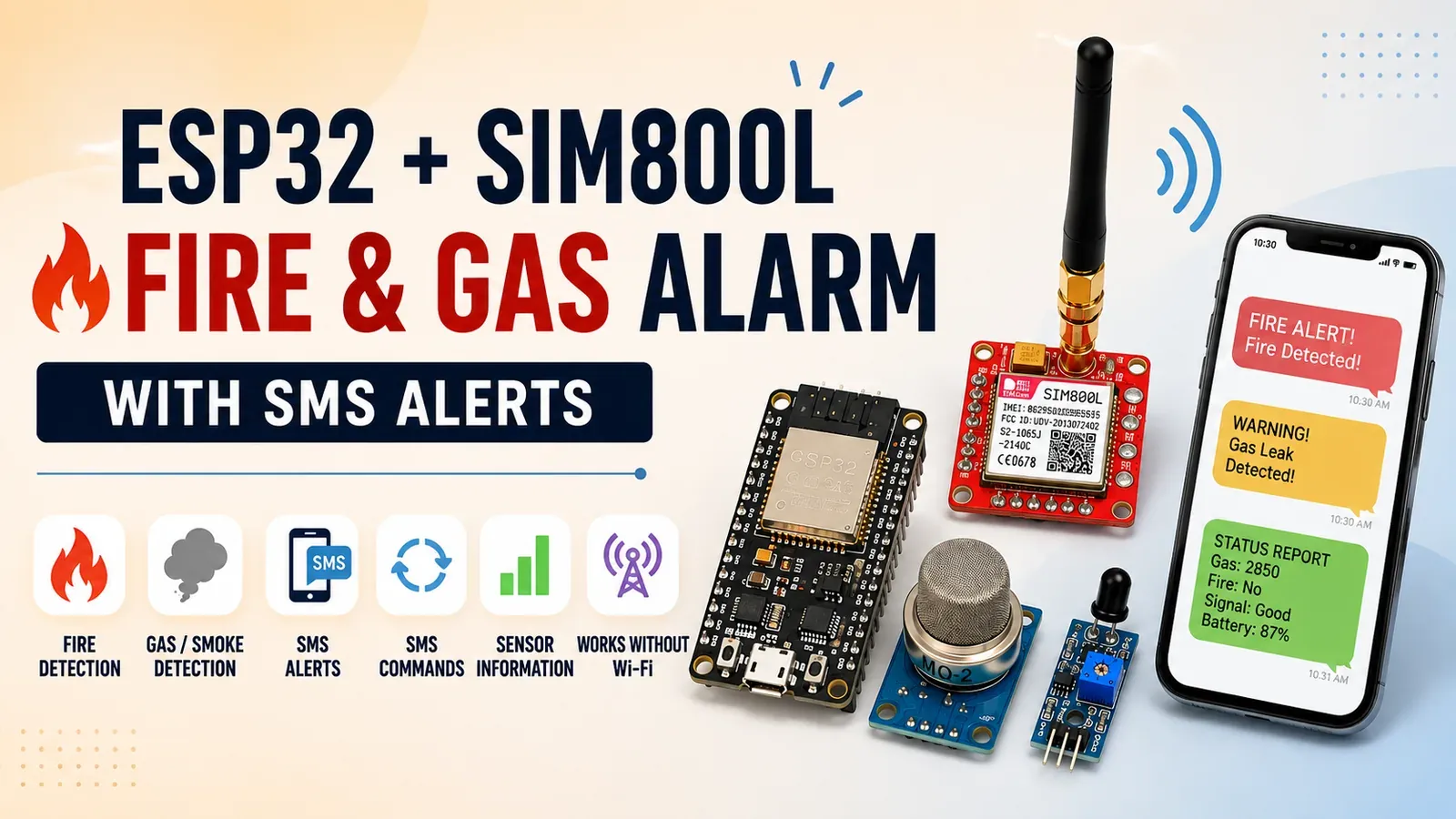
In this project, we will build a simple Fire and Gas Monitoring System using ESP32, SIM800L, an MQ-2 gas sensor, and a flame sensor.
The ESP32 continuously monitors the sensors. If it detects a fire or a high level of smoke/gas, it sends an SMS alert to a predefined phone number using the SIM800L GSM module.
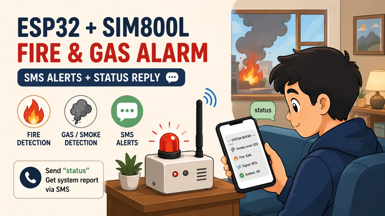
But there is one more useful feature: the system can also receive SMS commands. For example, you can send status to the device, and it will reply with the current smoke level, fire sensor status, and GSM signal information.
This makes the project a simple example of how an IoT device can communicate with a user without requiring Wi-Fi or a cloud server.
What We Are Building
The system has four main jobs:
- Monitor smoke/gas using an MQ-2 sensor.
- Monitor fire using an IR flame sensor.
- Send an SMS when a dangerous condition is detected.
- Respond to a
statusSMS with the current system condition.
The project uses the cellular network through the SIM800L, so the device does not need Wi-Fi or an internet connection for its basic alert functionality.
🎥 Watch the Full Project Video
If you prefer learning by watching the complete build, check out the full project video where I demonstrate the hardware, wiring, programming, and testing.
How the System Works
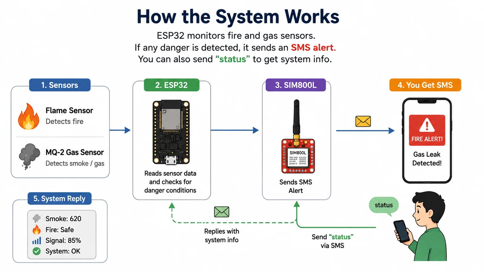
The ESP32 reads both sensors continuously.
If the flame sensor detects fire, the system immediately treats it as a critical condition.
If the MQ-2 reading goes above the configured threshold, the system treats it as a gas/smoke warning.
- The SIM800L then sends an SMS to the configured administrator number.
Main Features
Fire Detection
The flame sensor is connected to a digital GPIO pin. In this project, a LOW signal is treated as fire detected.
When fire is detected:
- The onboard LED turns on.
- A warning is printed to the Serial Monitor.
- An SMS alert is sent.
- A cooldown timer prevents repeated SMS messages every few seconds.
Gas and Smoke Detection
The MQ-2 provides an analog reading to the ESP32.
The project uses a configurable threshold:
const int SMOKE_THRESHOLD = 2500;If the sensor value becomes higher than this threshold, the ESP32 sends a gas/smoke warning SMS.
- The threshold should be adjusted according to your sensor, environment, and calibration.
SMS Alerts
The SIM800L handles communication with the cellular network.
When a dangerous condition is detected, the system can send messages such as:
URGENT ALERT: Fire Detected!
or:
WARNING: Smoke/Gas Leak Detected!The recipient number is configured in the source code:
#define ADMIN_NUMBER "+88017XXXXXXXX"- Replace this with your own phone number.
Two-Way SMS Communication
This is one of my favorite parts of the project.
The system doesn't only send SMS messages. It can also receive them.
Send:
statusto the SIM800L device.
The ESP32 reads the incoming SMS and replies with a system report containing information such as:
--- SYSTEM REPORT --- Power: ON Signal: XX% Smoke Level: XXXX (Limit: 2500) Fire Sensor: Safe- This gives you a simple way to remotely check the system.
SMS Cooldown
Imagine a fire continues for several minutes.
Without protection, the ESP32 could keep sending SMS messages continuously.
That would be annoying and could also create unnecessary SMS costs.
To avoid this, the project uses a 3-minute cooldown:
#define SMS_COOLDOWN 180000- The fire and smoke alerts have separate timers, so the device doesn't repeatedly send the same alert during a continuous event.
Components Required
Here are the main components used in this project. Amazon and AliExpress links are provided where available.
Affiliate Disclosure: Some links below are affiliate links. If you purchase through them, I may earn a small commission at no extra cost to you. This helps support more IoT projects and tutorials.
| Component | Purpose | Where to Buy |
|---|---|---|
| ESP32 Development Board | Main controller for the project | Amazon · AliExpress |
| SIM800L GSM Module | Sends and receives SMS over the cellular network | Amazon · AliExpress |
| MQ-2 Gas/Smoke Sensor | Detects smoke and combustible gases | Amazon · AliExpress |
| Flame Sensor Module | Detects the presence of a flame/fire | Amazon · AliExpress |
| 18650 Li-Ion Battery + Holder | Portable power source | Amazon · AliExpress |
| MT3608 DC-DC Step-Up Module | Boosts and regulates the battery voltage for the SIM800L | Amazon · AliExpress |
| 470µF 25V Capacitor | Helps stabilize the SIM800L power supply during current peaks | Amazon · AliExpress |
| Breadboard | Prototyping the circuit | — |
| Jumper / Connecting Wires | Connecting the components | — |
| Micro-USB Cable | Programming the ESP32 | — |
| Micro SIM Card | Provides cellular network connectivity | — |
⚡ Important: The 470µF capacitor is particularly useful for the SIM800L because GSM transmission can cause short current spikes. A stable power supply is essential for reliable SMS communication.
Prerequisites
This project is part of my GSM IoT Series, where we learn how to use the SIM800L with ESP32 and build practical GSM-based IoT projects.
Before connecting everything together, I recommend completing these three experiments first, especially if you're new to SIM800L.
Recommended Experiments
1. Connect SIM800L to ESP32
Start with the basics — wiring, UART communication, modem initialization, and connecting the SIM800L to the cellular network.
👉 Connect SIM800L to ESP32 — GSM Setup
2. Fix SIM800L Power & Network Issues
Learn about SIM800L power requirements, current spikes, network registration, antenna setup, and some of the most common GSM problems.
👉 SIM800L: Fix Power & Network Issues
3. Send & Receive SMS with ESP32
This project uses SMS for both fire/gas alerts and the remote status command, so understanding SMS communication beforehand will make this project much easier to follow.
👉 Send & Receive SMS with ESP32 and SIM800L
💡 Already familiar with SIM800L and SMS? You can skip these experiments and continue directly to the circuit connections below.
Once you're comfortable with these basics, let's connect all the components and build the complete fire and gas monitoring system.
Circuit Connections
Circuit Diagram
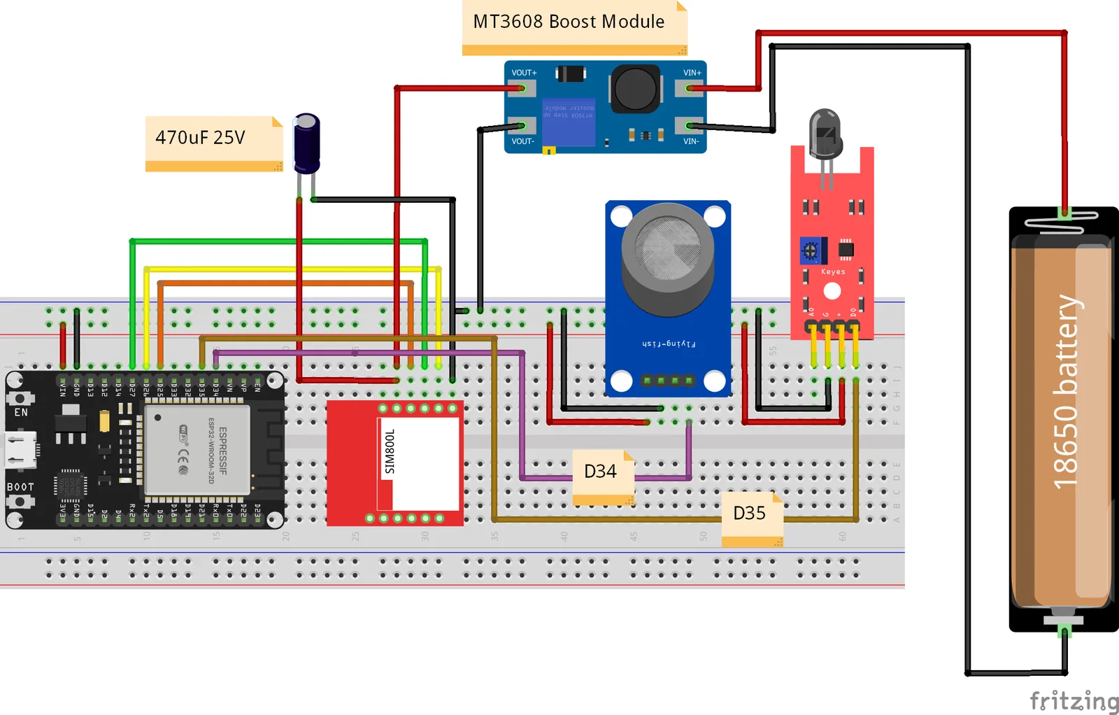
The project uses the following ESP32 pins:
| ESP32 Pin | Connected To | Purpose |
| GPIO 26 | SIM800L serial | GSM UART |
| GPIO 27 | SIM800L serial | GSM UART |
| GPIO 25 | SIM800L RST | Modem reset |
| GPIO 34 | MQ-2 A0 | Analog smoke/gas reading |
| GPIO 35 | Flame Sensor D0 | Digital fire detection |
| GPIO 2 | Onboard LED | Status indication |
| GND | Common GND | Ground |
The firmware defines GPIO 26 and 27 as the modem UART pins, GPIO 25 as reset, GPIO 34 for the MQ-2 analog input, and GPIO 35 for the flame sensor.
Common Ground
Make sure the following share a common ground:
ESP32 GND
   │
   ├── SIM800L GND
   ├── MQ-2 GND
   ├── Flame Sensor GND
   └── Power Supply GND
A missing common ground can cause unreliable serial communication and sensor readings.
Facing difficulties connecting the SIM800L
If you are new to the ESP32 + SIM800L connection, check the dedicated GSM setup tutorial before continuing.
Connect SIM800L to ESP32 — GSM Setup
Software Requirements
Before starting the project, make sure your development environment is ready.
Software Tools
- Arduino IDE: Make sure you have the latest version of the Arduino IDE installed.
ESP32 Board Support: Install the ESP32 board package through the Arduino IDE's Boards Manager.
Need help setting it up? Check out my guide:
👉 How to Set Up ESP32 in Arduino IDE 2.0 (Windows/Ubuntu)- TinyGSM Library: This library is used to communicate with the SIM800L GSM module. You can install it directly from the Arduino IDE Library Manager.
- StreamDebugger: This library is useful for debugging the communication between the ESP32 and SIM800L while developing the project.
📦 Required Arduino Libraries
Before uploading the code, make sure these libraries are installed:
| Library | Purpose |
|---|---|
| TinyGSM | Communication with the SIM800L GSM module |
| StreamDebugger | Helps debug GSM/AT command communication |
You can install both libraries from:
Arduino IDE → Sketch → Include Library → Manage Libraries
Search for the library name and click Install.
Get the Complete Project Code
The complete source code for this project is available on GitHub.
Instead of copying the code from this article, I recommend downloading or cloning the repository so you always have the latest version of the project.
🔗 GitHub Repository
👉 ESP32 SIM800L Fire & Gas SMS Alert — GitHub
The repository includes:
- Complete Arduino source code
- Project documentation
- Circuit/wiring diagram
- Required library information
- Configuration details
Copy the code
#define TINY_GSM_MODEM_SIM800
#define SerialMon Serial
#define SerialAT Serial1
#define TINY_GSM_DEBUG SerialMon
#define GSM_PIN ""

#include <TinyGsmClient.h>

// --- USER CONFIGURATION ---
#define ADMIN_NUMBER ""  // REPLACE WITH YOUR NUMBER
#define SMS_COOLDOWN 180000            // 3 Minutes (180000ms) between alert SMS to prevent spam

// --- PINS ---
#define MODEM_TX 26
#define MODEM_RX 27
#define MODEM_RST 25
#define MQ2_PIN 34    // Analog Pin for Smoke
#define FLAME_PIN 35  // Digital Pin for Fire (0 = Fire detected usually)
#define LED_PIN 2     // Onboard LED for status

// --- THRESHOLDS ---
const int SMOKE_THRESHOLD = 2500;  // Adjust based on your MQ2 calibration (0-4095)

#ifdef DUMP_AT_COMMANDS
#include <StreamDebugger.h>
StreamDebugger debugger(SerialAT, SerialMon);
TinyGsm modem(debugger);
#else
TinyGsm modem(SerialAT);
#endif

TinyGsmClient client(modem);

// Variables
String received_message = "";
String sender_number = "";
bool isReceivingMessage = false;

// Timer Variables for non-blocking alerts
unsigned long lastFireSmsTime = 0;
unsigned long lastSmokeSmsTime = 0;

// Function Prototypes
String extractPhoneNumber(String response);
void handleSms(String number, String msg);
void checkSensors();

void setup() {
  SerialMon.begin(115200);
  delay(100);

  // Sensor Setup
  pinMode(MQ2_PIN, INPUT);
  pinMode(FLAME_PIN, INPUT);
  pinMode(LED_PIN, OUTPUT);
  digitalWrite(LED_PIN, LOW);

  // Modem Setup
  pinMode(MODEM_RST, OUTPUT);
  digitalWrite(MODEM_RST, LOW);
  delay(100);
  digitalWrite(MODEM_RST, HIGH);
  delay(3000);

  SerialMon.println("Wait ...");
  SerialAT.begin(115200, SERIAL_8N1, MODEM_TX, MODEM_RX);
  delay(3000);
  SerialMon.println("Initializing modem ...");
  modem.restart();
  delay(3000);
  modem.init();
  if (GSM_PIN && modem.getSimStatus() != 3) {
    modem.simUnlock(GSM_PIN);
  }
  String modemInfo = modem.getModemInfo();
  SerialMon.print("Modem Info: ");
  SerialMon.println(modemInfo);
  SerialMon.print("Waiting for network...");
  if (!modem.waitForNetwork()) {
    SerialMon.println(" fail");
    delay(10000);  // wait 10s, for connected to network successfully
    return;
  }
  SerialMon.println(" success");
  if (modem.isNetworkConnected()) {
    DBG("Network connected");
  }
  String imei = modem.getIMEI();
  SerialMon.print("IMEI: ");
  SerialMon.println(imei);
  String operatorName = modem.getOperator();
  SerialMon.print("Operator: ");
  SerialMon.println(operatorName);
  int signalQuality = modem.getSignalQuality();  // Signal quality (0–31, 99 = not known)
  SerialMon.print("Signal Quality (0-31): ");
  SerialMon.println(signalQuality);
  SerialMon.println("Enabling network time synchronization...");

  // Sync Time for timestamps
  modem.sendAT("+CLTS=1");
  modem.sendAT("&W");

  // SMS Mode
  modem.sendAT("+CMGF=1");
  delay(1000);
  SerialAT.print("AT+CNMI=2,2,0,0,0\r");
  delay(1000);

  // Notify Boot
  SerialMon.println("System Online. Sending Boot SMS...");
  modem.sendSMS(ADMIN_NUMBER, "IoT System Online: Fire & Gas Monitoring Active.");
}

void loop() {
  // 1. Check for Incoming SMS
  while (SerialAT.available()) {
    String response = SerialAT.readStringUntil('\n');
    response.trim();
    if (response.startsWith("+CMT: ")) {
      sender_number = extractPhoneNumber(response);
      isReceivingMessage = true;
    } else if (isReceivingMessage) {
      received_message = response;
      isReceivingMessage = false;
      received_message.trim();
      received_message.toLowerCase();
      handleSms(sender_number, received_message);
    }
  }

  // 2. Check Sensors
  checkSensors();
}

void checkSensors() {
  int smokeValue = analogRead(MQ2_PIN);
  int flameValue = digitalRead(FLAME_PIN);  // Usually LOW (0) means Fire detected for these modules

  // --- FIRE DETECTION LOGIC ---
  if (flameValue == LOW) {  // Fire Detected
    digitalWrite(LED_PIN, HIGH);
    SerialMon.println("CRITICAL: FIRE DETECTED!");

    // Check if we can send SMS (Cooldown logic)
    if (millis() - lastFireSmsTime > SMS_COOLDOWN || lastFireSmsTime == 0) {
      String alertMsg = "URGENT ALERT: Fire Detected! Sensor Value: " + String(flameValue);
      modem.sendSMS(ADMIN_NUMBER, alertMsg);
      SerialMon.println("Fire SMS Sent.");
      lastFireSmsTime = millis();
    }
  }

  // --- SMOKE DETECTION LOGIC ---
  else if (smokeValue > SMOKE_THRESHOLD) {
    digitalWrite(LED_PIN, HIGH);
    SerialMon.print("WARNING: High Gas/Smoke Level: ");
    SerialMon.println(smokeValue);

    if (millis() - lastSmokeSmsTime > SMS_COOLDOWN || lastSmokeSmsTime == 0) {
      String alertMsg = "WARNING: Smoke/Gas Leak Detected! Level: " + String(smokeValue);
      modem.sendSMS(ADMIN_NUMBER, alertMsg);
      SerialMon.println("Smoke SMS Sent.");
      lastSmokeSmsTime = millis();
    }
  }

  // --- NORMAL STATE ---
  else {
    digitalWrite(LED_PIN, LOW);
  }
}

void handleSms(String number, String msg) {
  SerialMon.print("SMS From: ");
  SerialMon.println(number);
  SerialMon.print("Message: ");
  SerialMon.println(msg);

  if (msg == "status") {
    // Read current sensor values for the report
    int currentSmoke = analogRead(MQ2_PIN);
    int currentFlame = digitalRead(FLAME_PIN);
    int signal = modem.getSignalQuality();
    String operatorName = modem.getOperator();

    String statusMsg = "--- SYSTEM REPORT ---\n";
    statusMsg += "Power: ON\n";
    statusMsg += "Signal: " + String(signal) + "%\n";
    statusMsg += "Smoke Level: " + String(currentSmoke) + " (Limit: " + String(SMOKE_THRESHOLD) + ")\n";
    statusMsg += "Fire Sensor: " + String(currentFlame == LOW ? "DETECTED!" : "Safe") + "\n";

    modem.sendSMS(number, statusMsg);
    SerialMon.println("Status Report Sent.");
  } else {
    modem.sendSMS(number, "Unknown Command. Send 'status' to get sensor data.");
  }
}

String extractPhoneNumber(String response) {
  int startIndex = response.indexOf("\"") + 1;
  int endIndex = response.indexOf("\",", startIndex);
  return response.substring(startIndex, endIndex);
}
Code Configuration
Before uploading the code to your ESP32, there are a few settings you need to configure.
Open the project folder and locate the main Arduino file:
fire_and_gas_protection_via_sms.ino1. Set Your Phone Number
Find the following line in the code:
#define ADMIN_NUMBER "+88017XXXXXXXX"Replace the example number with the phone number that should receive the alerts.
For example:
#define ADMIN_NUMBER "+8801XXXXXXXXX"Use the international format for your phone number.
This number will receive:
- 🔥 Fire alerts
- 💨 Smoke/gas alerts
- 📡 System startup notification
- 📊
statusresponses
2. Configure the SMS Cooldown
The project includes a cooldown period to prevent the system from sending the same alert repeatedly.
The default value is:
#define SMS_COOLDOWN 180000The value is in milliseconds, so:
180000 ms = 180 seconds = 3 minutesThis means that if a fire remains detected continuously, the system won't keep sending SMS messages every few seconds.
You can change this value if required.
For example, a 1-minute cooldown would be:
#define SMS_COOLDOWN 60000💡 Recommendation: Keep the default 3-minute cooldown while testing the project. You can adjust it later depending on your application.
3. Configure the Smoke/Gas Threshold
The MQ-2 sensor threshold is defined in the code:
const int SMOKE_THRESHOLD = 2500;If the MQ-2 reading goes above this value, the system considers it a smoke/gas warning.
However, 2500 is not a universal value. MQ-2 readings can vary depending on the sensor, environment, warm-up time, and power supply.
For your own hardware, monitor the sensor readings through the Serial Monitor and adjust the threshold accordingly.
4. Check the SIM800L Configuration
The project is configured for the SIM800L GSM module using TinyGSM.
The firmware uses the ESP32 hardware serial interface to communicate with the modem.
The current pin configuration is:
#define MODEM_TX 26
#define MODEM_RX 27
The modem reset pin is:
#define MODEM_RST 25These pins match the wiring used in this project.
⚠️ Important: If you change the wiring, make sure the corresponding GPIO definitions in the code are changed as well.
5. Select Your ESP32 Board
In Arduino IDE, select the ESP32 board you are using.
For a typical ESP32-WROOM development board, you can use:
Tools → Board → ESP32 Arduino → ESP32 Dev ModuleThen select the appropriate COM port:
Tools → Port → Your ESP32 COM Port6. Upload the Firmware
Once the configuration is complete:
- Connect the ESP32 to your computer using a USB cable.
- Select the correct ESP32 board.
- Select the correct COM port.
- Click Verify to compile the project.
- Click Upload.
- Open the Serial Monitor at 115200 baud.
If everything is configured correctly, the ESP32 will start initializing the SIM800L and attempting to connect to the GSM network.
Expected Result
After uploading the code and completing the hardware setup, the system is ready to monitor the environment.
When everything is working correctly:
- 🔥 The flame sensor detects fire and triggers an urgent SMS alert.
- 💨 The MQ-2 detects high smoke/gas levels and sends a warning SMS.
- 📱 The SIM800L delivers the alerts to the configured phone number.
- 🔄 Sending
statusto the device returns the current system information. - ⏱️ The SMS cooldown helps prevent repeated alerts during a continuous event.
The device also sends a startup SMS when the GSM connection is successfully initialized, letting you know that the monitoring system is online.
📱 Example Alert
When fire is detected, you will receive an SMS similar to:
URGENT ALERT: Fire Detected!
For smoke or gas detection:
WARNING: Smoke/Gas Leak Detected!
Level: 2800
And when you send:
status
the device responds with the current system condition.
🎥 See the Project in Action
⚠️ Important Safety Note
Conclusion
In this project, we combined a few simple components to build a useful GSM-based safety monitoring system.
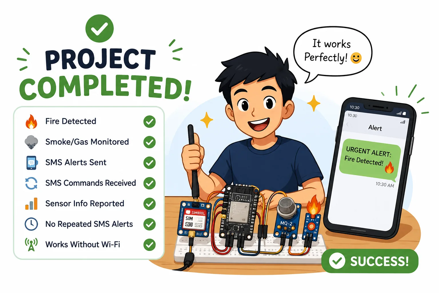
Using an ESP32, SIM800L, MQ-2 gas sensor, and flame sensor, the system can:
More GSM IoT Projects
If you enjoyed this project, continue exploring the GSM IoT Series:
Connect SIM800L to ESP32 — GSM Setup
SIM800L: Fix Power & Network Issues