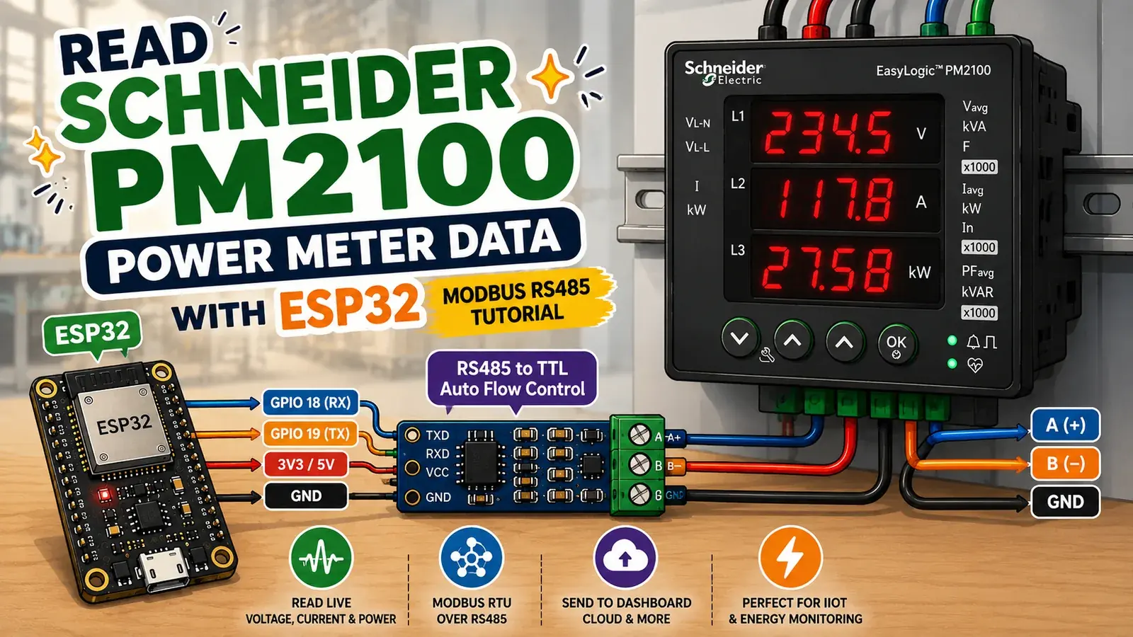
Introduction
Industrial energy meters like the Schneider Electric EasyLogic PM2100 are everywhere — in electrical panels, factories, and buildings — quietly measuring voltage, current, power, and frequency.
But what if you could pull that data into your own ESP32 and send it anywhere — a web dashboard, the cloud, or even your home automation system?
In this tutorial, that's exactly what we'll do.
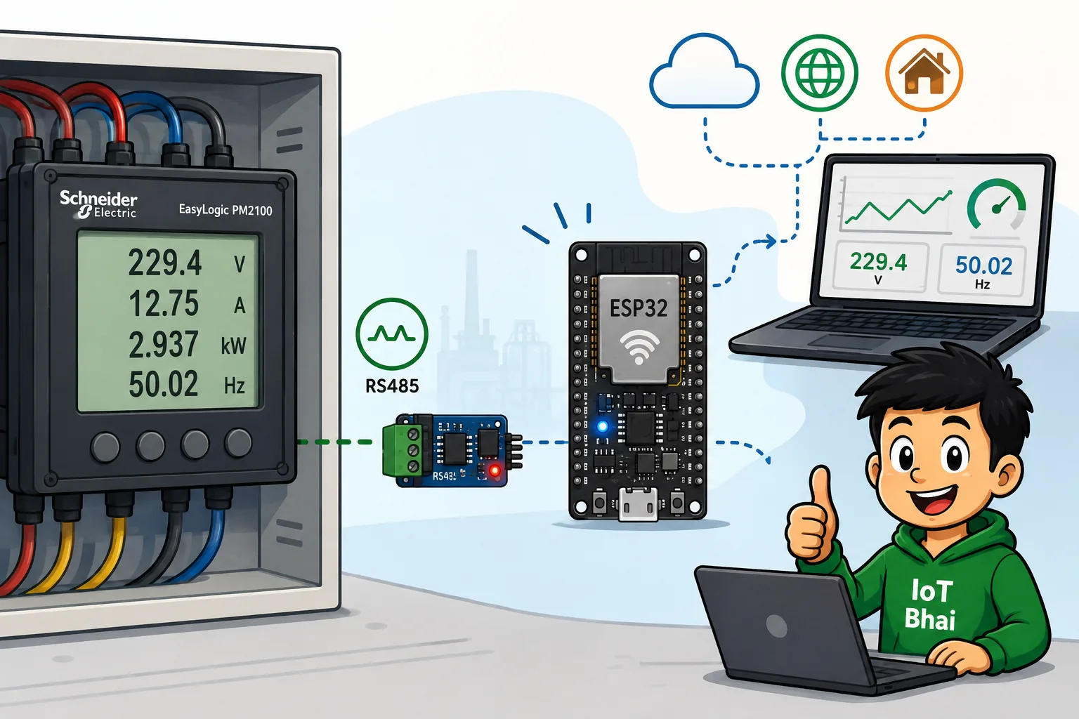
We'll connect an ESP32 to a Schneider PM2100 using a simple RS485-to-TTL module and read live voltage and frequency data over the Modbus RTU protocol.
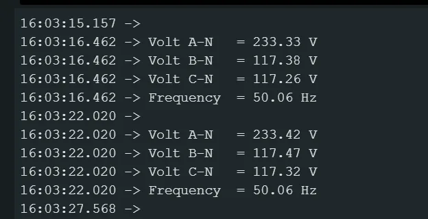
By the end, your Serial Monitor should show real values directly from the meter:
Volt A-N   = 233.33 V
Volt B-N   = 117.38 V
Volt C-N   = 117.26 V
Frequency  = 50.06 Hz
Let's get started. ⚡
📺 Prefer video?
Watch the full step-by-step build on the
What is Modbus RTU?
Modbus is a simple industrial communication protocol. Think of it as a language that machines use to ask each other for data.
In our project:
- The master — our ESP32 — asks a question: "Give me the value at register 3027."
- The slave — the PM2100 meter — answers with the data.
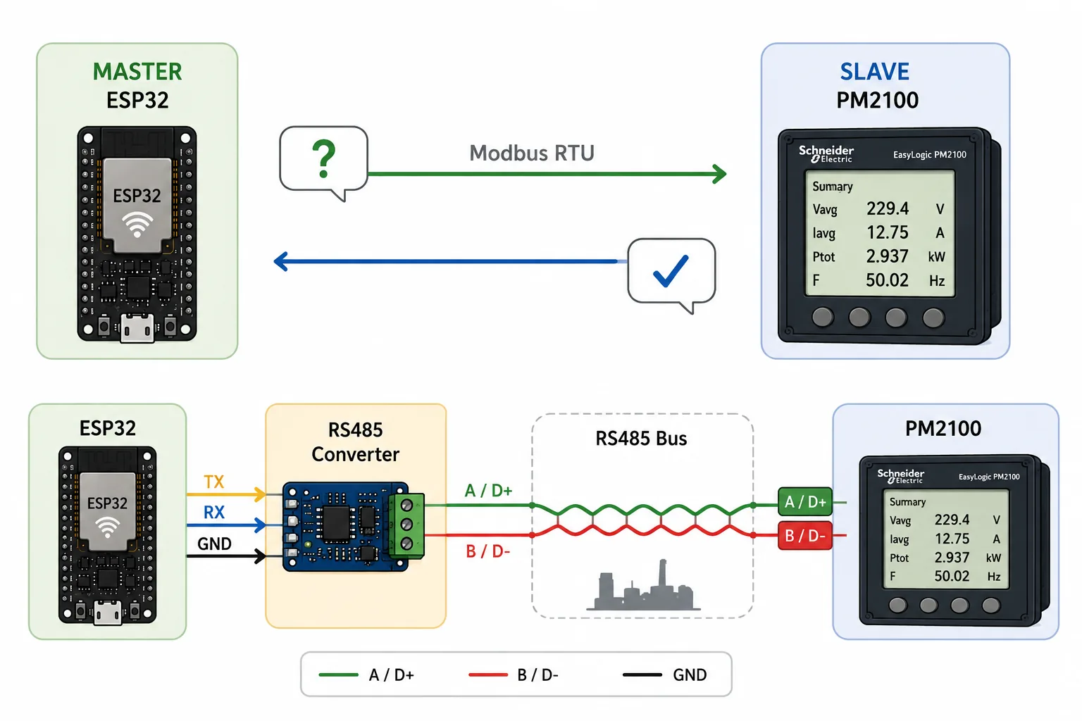
Modbus RTU runs over a serial communication line. In this project, we're using RS485, a rugged electrical standard designed to work reliably over long distances and in electrically noisy industrial environments.
RS485 uses two main communication wires:
- A / D+
- B / D−
The ESP32 itself uses TTL-level UART, so it can't communicate directly with the RS485 bus. That's where our small RS485-to-TTL converter comes in.
It translates the ESP32's UART signals into RS485 signals that the PM2100 can understand.
What You'll Need
| Component | Qty | Notes | Where to Buy |
|---|---|---|---|
| ESP32 dev board | 1 | Any ESP32 with hardware Serial2 | AliExpress | Amazon |
| RS485 to TTL module | 1 | Auto flow-control (auto-direction) type recommended | AliExpress | Amazon |
| Schneider PM2100 | 1 | With Modbus RTU communication enabled | — |
| Jumper wires | few | For connections | — |
| 120 Ω resistor | 1 | Termination for long cable runs (optional on the bench) | — |
The store links above are affiliate links — using them supports the IoT Bhai channel at no extra cost to you. Thank you! 🙏
RS485 to TTL Module Pinout
Before we connect everything to the ESP32, let's take a quick look at the RS485-to-TTL module used in this project.
This is an automatic flow-control (auto-direction) module, so it handles the switching between transmit and receive automatically. That means we don't need to control separate DE and RE pins from the ESP32.
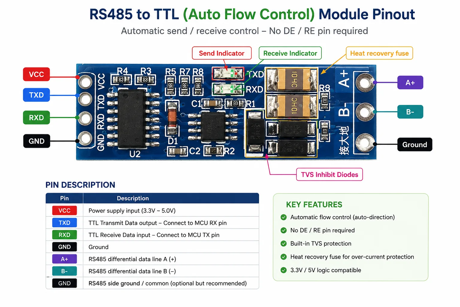
The module provides simple TTL-side pins for the ESP32 and RS485-side pins for connecting to the PM2100.
Circuit Design
Now that we understand the RS485-to-TTL module pins, let's put everything together.
The circuit is quite simple. The ESP32 communicates with the RS485 module using its hardware UART, while the RS485 side of the module connects directly to the A and B terminals of the Schneider PM2100.
The automatic flow-control feature of the RS485 module means we don't need any additional GPIO pins for controlling the transmit and receive direction.
Complete Circuit Connection
Connection Summary
| ESP32 | RS485-to-TTL Module | PM2100 |
|---|---|---|
| GPIO 18 (RX) | TXD | — |
| GPIO 19 (TX) | RXD | — |
| 3V3 / 5V | VCC | — |
| GND | GND | — |
| — | A+ | A (+) |
| — | B− | B (−) |
| — | GND | Shield / common (optional) |
The important connections are GPIO 18 → TXD, GPIO 19 → RXD, and A+ / B− → the PM2100's A / B terminals.
💡 Remember: The TX and RX connections are crossed because TX sends data and RX receives it. On the RS485 side, start with A → A and B → B. If communication doesn't work, swapping the A and B wires is one of the first things to test.
Software Requirements
Before starting the project, make sure your development environment is ready.
Software Tools
- Arduino IDE: Make sure you have the latest version of the Arduino IDE installed.
ESP32 Board Support: Install the ESP32 board package through the Arduino IDE's Boards Manager.
Need help setting it up? Check out my guide:
👉 How to Set Up ESP32 in Arduino IDE 2.0 (Windows/Ubuntu)
Configure the Meter's Communication Settings
This is one of the steps that's easy to miss.
The ESP32 and PM2100 must use the same serial communication settings. If they don't, you'll usually get Modbus read errors.
For this project, the meter is configured as follows:
| Setting | Value |
|---|---|
| Slave / Meter ID | 1 |
| Baud rate | 19200 |
| Parity / Frame | 8E1 |
| Protocol | Modbus RTU |
8E1 means:
- 8 data bits
- Even parity
- 1 stop bit
If your PM2100 uses different settings, simply change the corresponding values in the ESP32 code.
Understanding the Register Map
The PM2100 stores measurements in memory locations called registers.
Here's the important part: each measurement we're reading is a 32-bit floating-point value, while a single Modbus register contains only 16 bits.
So each measurement requires 2 Modbus registers.
For this project, we're reading:
| Parameter | Starting Register |
|---|---|
| Voltage A-N | 3027 |
| Voltage B-N | 3029 |
| Voltage C-N | 3031 |
| Frequency | 3109 |
For example, voltage A-N starts at register 3027, so the ESP32 reads registers 3027 and 3028.
The two 16-bit values are then combined into one 32-bit value and interpreted as an IEEE-754 floating-point number.
Don't worry — the code handles all of this for us.
The Code
Before uploading the code, install the ModbusMaster library.
In Arduino IDE:
Tools → Manage Libraries → Search ModbusMaster → Install
Full project GitHub link: schneider-pm2100-esp32-modbus on GitHub
Upload this sketch:
/*
 * ============================================================
 *  Schneider PM2100 Energy Meter -> ESP32 (Modbus RTU / RS485)
 * ============================================================
 *  Reads live data from a Schneider PM2100 power meter using
 *  an ESP32 and an RS485-to-TTL converter (auto flow-control).
 *
 *  Values read (32-bit float, 2 registers each):
 *    - Voltage A-N
 *    - Voltage B-N
 *    - Voltage C-N
 *    - Frequency
 *
 *  Library: ModbusMaster  ->  https://github.com/4-20ma/ModbusMaster
 *  Channel: IoT Bhai
 * ============================================================
 */

#include <ModbusMaster.h>

/* -------------------- Meter settings -------------------- */
#define METER_ID    1          // Modbus slave address of the PM2100
#define TOTAL_REG   4          // Number of parameters we read

// PM2100 register addresses (each value = 2 registers = 1 float)
#define REG_AN   3027          // Voltage A-N
#define REG_BN   3029          // Voltage B-N
#define REG_CN   3031          // Voltage C-N
#define REG_FQ   3109          // Frequency

uint16_t reg_addr[TOTAL_REG] = {
  REG_AN,
  REG_BN,
  REG_CN,
  REG_FQ,
};

float DATA_METER[TOTAL_REG];   // Latest values read from the meter

/* -------------------- RS485 / Modbus wiring -------------------- */
#define MODBUS_RX_PIN       18         // ESP32 RX  ->  RO (or TXD) of RS485 module
#define MODBUS_TX_PIN       19         // ESP32 TX  ->  DI (or RXD) of RS485 module
#define MODBUS_SERIAL_BAUD  19200      // Must match the meter's baud rate
#define PARITY              SERIAL_8E1 // 8 data bits, Even parity, 1 stop bit

// ModbusMaster object (our node/master)
ModbusMaster node;

/* -------------------- Helpers -------------------- */
// Reinterpret a 32-bit value as an IEEE-754 float
float HexToFloat(uint32_t x) {
  return (*(float*)&x);
}

// Read one float parameter (2 registers) from the meter
float read_meter_float(uint16_t reg) {
  uint16_t data[2];
  uint32_t value = 0;

  uint8_t result = node.readHoldingRegisters(reg, 2);
  delay(500);

  if (result == node.ku8MBSuccess) {
    data[0] = node.getResponseBuffer(0);   // high word
    data[1] = node.getResponseBuffer(1);   // low word

    value = ((uint32_t)data[0] << 16) | data[1];
    return HexToFloat(value);
  } else {
    Serial.print("Modbus read failed. REG >>> ");
    Serial.println(reg);
    delay(500);
    return 0;
  }
}

// Read all parameters into DATA_METER[]
void get_meter() {
  delay(500);
  for (uint8_t i = 0; i < TOTAL_REG; i++) {
    DATA_METER[i] = read_meter_float(reg_addr[i]);
  }
}

/* -------------------- Setup -------------------- */
void setup() {
  // Serial monitor
  Serial.begin(115200);

  // Serial2 for RS485 communication -> Serial2.begin(baud, protocol, RX, TX)
  Serial2.begin(MODBUS_SERIAL_BAUD, PARITY, MODBUS_RX_PIN, MODBUS_TX_PIN);
  Serial2.setTimeout(200);

  // Bind the Modbus node to the meter address and Serial2 (once)
  node.begin(METER_ID, Serial2);
}

/* -------------------- Loop -------------------- */
void loop() {
  get_meter();

  Serial.println();
  Serial.print("Volt A-N   = "); Serial.print(DATA_METER[0]); Serial.println(" V");
  Serial.print("Volt B-N   = "); Serial.print(DATA_METER[1]); Serial.println(" V");
  Serial.print("Volt C-N   = "); Serial.print(DATA_METER[2]); Serial.println(" V");
  Serial.print("Frequency  = "); Serial.print(DATA_METER[3]); Serial.println(" Hz");

  delay(3000);
}
Upload and Test
Now let's test the setup.
Step 1 — Select the ESP32
In Arduino IDE, select your ESP32 board and the correct COM port.
Step 2 — Upload
Click Upload and wait for the upload to finish.
Step 3 — Open Serial Monitor
Open the Serial Monitor and set the baud rate to:
115200If everything is connected and configured correctly, you should see live readings similar to:
🎉 And that's it — your ESP32 is now reading live data directly from an industrial power meter.
How the Code Works
Let's break down the important parts.
1. Start the ESP32 UART
Serial2.begin(MODBUS_SERIAL_BAUD, PARITY, MODBUS_RX_PIN, MODBUS_TX_PIN);This starts the ESP32's second hardware serial port using:
- 19200 baud
8E1frame- GPIO 18 as RX
- GPIO 19 as TX
These settings must match the PM2100.
2. Set the Modbus slave ID
node.begin(METER_ID, Serial2);Here, METER_ID is 1, so the ESP32 communicates with Modbus slave address 1.
3. Read two registers
node.readHoldingRegisters(reg, 2);Because each measurement is stored as a 32-bit float, we request 2 × 16-bit registers.
4. Combine the two 16-bit words
value = ((uint32_t)data[0] << 16) | data[1];The first register becomes the high 16 bits and the second register becomes the low 16 bits.
Together, they form the original 32-bit value.
5. Convert the bits into a float
return HexToFloat(value);HexToFloat() interprets the 32-bit value as an IEEE-754 floating-point number.
That's what gives us the actual voltage or frequency instead of a raw register value.
6. Refresh the readings
The loop() function reads all four parameters and prints them to the Serial Monitor.
The readings are refreshed every few seconds.
Troubleshooting
| Problem | Likely Cause / Fix |
|---|---|
Modbus read failed. REG >>> ... | Check baud rate, parity, meter ID, and A/B wiring |
All readings are 0 | Check that the meter is powered and responding |
| Garbage or jumpy values | Try a 120 Ω termination resistor and check the wiring |
| No communication | Try swapping RS485 A and B |
| Wrong numbers | Confirm the register addresses match your meter configuration/firmware |
| Nothing appears in Serial Monitor | Check the Serial Monitor baud rate — it should be 115200 |
When troubleshooting Modbus, don't change ten things at once. Check the communication settings first, then the RS485 wiring, then the register addresses.
Wrapping Up
You've just built a small bridge between the industrial world and the maker world — reading a real Schneider PM2100 power meter with an ESP32 over Modbus RS485.
What makes this useful is that we're not just displaying a sensor value. We're taking data from a real industrial energy meter and making it available to the ESP32, which means we can now send it to dashboards, databases, cloud platforms, or automation systems.
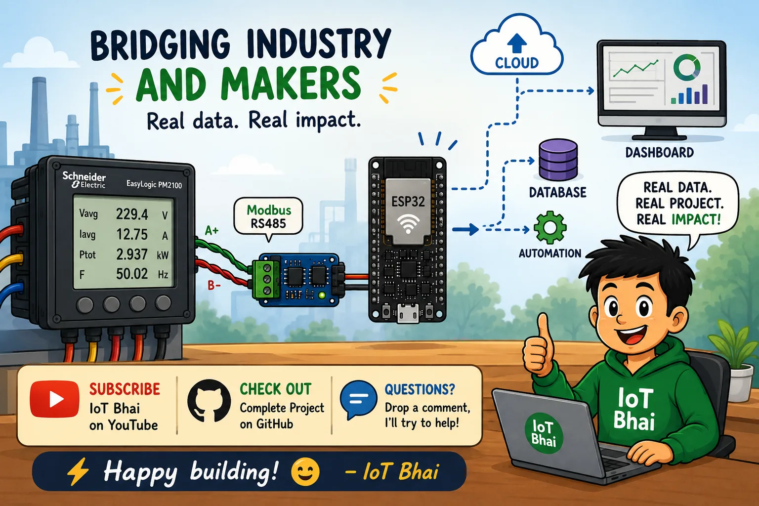
That's a genuinely useful building block for IoT, energy monitoring, industrial automation, and IIoT projects.
If this tutorial helped you, subscribe to IoT Bhai on YouTube and check out the complete project on GitHub.
Got questions or ran into a Modbus issue? Drop them in the comments — I'll try to help.
Happy building! ⚡
— IoT Bhai
Join the discussion
Got a question, hit an error, or built this yourself? Share it below — sign in with GitHub to comment.